Chapter 54: Wind Turbine Manufacturing |
Summary |
Wind turbine manufacturing represents one of the most demanding and rapidly evolving sectors in modern heavy industry. The scale of components, the precision required, and the harsh environments in which these machines must operate create unique challenges for industrial robotics. This chapter examines how robotic systems are deployed across the wind turbine manufacturing supply chain, from blade production and nacelle assembly to tower fabrication and on-site installation. A particular focus is placed on mobile robot assistants that provide laser guidance for cable tray assembly, a recent innovation that reduced processing time by 37 percent, from 40 minutes to 25 minutes, without requiring manual adjustments. The chapter explores applications in multiple industries where similar robotic solutions have been adapted, including aerospace, shipbuilding, construction, and heavy machinery. By examining these cross-sector applications, readers will understand how robotic technologies developed for wind turbine manufacturing often find broader industrial relevance, and how lessons from other industries feed back into wind energy production. |

|
1. Introduction to Wind Turbine Manufacturing |
Wind turbine manufacturing sits at the intersection of several heavy industries. It borrows from aerospace for blade design, from shipbuilding for large-scale steel fabrication, from automotive for nacelle assembly, and from construction for tower erection. The result is a manufacturing ecosystem that must handle some of the largest single components produced by human industry while maintaining tolerances measured in fractions of a millimeter. |
A modern utility-scale wind turbine can have a rotor diameter exceeding 200 meters. Each blade can weigh over 50 tons. The nacelle, which houses the generator, gearbox, and control systems, can weigh more than 100 tons. The tower can rise over 150 meters. These are not products that can be assembled on a conventional conveyor belt. They require specialized facilities, custom tooling, and increasingly, advanced robotic systems. |
The role of robotics in wind turbine manufacturing has grown dramatically over the past two decades. Initially, robots were used primarily for repetitive tasks such as welding tower sections or applying gelcoat to blade molds. Today, robots perform complex operations including precision drilling, automated fiber placement, laser-guided assembly, and even on-site maintenance and inspection. |
What makes wind turbine manufacturing particularly interesting from a robotics perspective is the diversity of environments in which the robots must operate. A factory producing blade roots may be climate-controlled and clean. A facility assembling nacelles may involve heavy overhead cranes and moving production lines. A tower fabrication shop may be dusty and hot. And the final installation site may be offshore, exposed to salt spray and wind, or on a remote mountain ridge accessible only by gravel roads. |
This chapter focuses on one specific but highly representative application: mobile robot assistants that project laser guidance for cable tray assembly. This application demonstrates how relatively simple robotic technology, when properly integrated, can produce significant productivity gains. It also illustrates the broader principle that in wind turbine manufacturing, the most successful robotic solutions are often those that assist human workers rather than replace them entirely. |

|
2. The Cable Tray Assembly Challenge |
Cable trays are the metal or plastic structures that support and route electrical cables throughout a wind turbine. In a modern turbine, hundreds of meters of cable tray are installed in the tower, nacelle, and hub. These trays carry power cables from the generator to the transformer, control cables from the controller to the pitch systems, and communication cables between various sensors and the supervisory control and data acquisition system. |
The assembly of cable trays is a task that appears simple but is in fact quite complex. Each tray section must be positioned correctly, aligned with adjacent sections, and secured to the tower structure. The trays must follow precise paths to avoid interference with other components. They must be grounded properly to prevent electrical hazards. And they must be installed in a sequence that allows access for workers and equipment. |
Traditionally, cable tray assembly in wind turbine manufacturing has been a manual process. Workers climb into the tower, measure the required positions, mark the locations, drill holes, and bolt the trays into place. This process is time-consuming, physically demanding, and prone to error. A single misplaced hole can require rework that delays the entire production schedule. |
In a typical tower section, cable tray assembly might take 40 minutes per section. With multiple sections per tower and multiple towers per project, the total time adds up quickly. Even a small reduction in assembly time can produce significant cost savings. |
The challenge is compounded by the geometry of the tower. Wind turbine towers are tapered cylinders. The interior surface is curved. The cable trays must follow the curve while maintaining a consistent distance from the wall. Workers must measure and mark positions on a curved surface, often while standing on scaffolding or working from a lift. |
|
3. Mobile Robot Assistants with Laser Guidance |
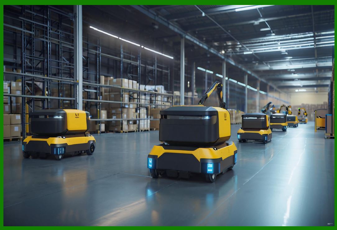
The mobile robot assistant with laser guidance is a solution designed specifically for this challenge. The system consists of a mobile base that can move along the interior of the tower, a robotic arm or gantry that can position a laser projector, and a control system that calculates the correct positions for cable tray mounting points. |
The operation is straightforward in concept. The robot moves to a predetermined position within the tower section. The laser projector projects a pattern onto the interior surface of the tower. This pattern indicates exactly where holes should be drilled, where brackets should be mounted, and where cable tray sections should be aligned. Workers then follow the laser guidance to perform the actual installation. |
What makes this system effective is that it eliminates the need for manual measurement and marking. Workers no longer need to use tape measures, levels, and chalk lines. They simply follow the laser projection. This reduces the cognitive load on workers, speeds up the process, and improves accuracy. |
The laser guidance system also eliminates the need for manual adjustments. In traditional assembly, workers often need to adjust the position of cable trays after initial placement to ensure proper alignment. With laser guidance, the correct position is indicated from the start, so adjustments are minimized or eliminated entirely. |
The result, as noted in the chapter summary, is a reduction in processing time from 40 minutes to 25 minutes per tower section. This represents a 37 percent improvement in productivity. For a wind turbine manufacturer producing hundreds of towers per year, this translates into thousands of hours of labor saved and millions of dollars in cost reduction. |

|
4. Technical Details of the Laser Guidance System |
To understand how this system works, it is helpful to examine its components in more detail. |
The mobile base is typically a wheeled or tracked platform that can navigate the interior of the tower. Because the tower is a curved surface, the base must be able to maintain a stable position and orientation. Some systems use magnetic wheels that attach to the steel tower wall. Others use a rail system that is temporarily installed inside the tower. Still others use a combination of wheels and suction cups. |
The robotic arm or gantry provides the articulation needed to position the laser projector. In some systems, the arm is a simple two-axis positioner. In others, it is a multi-axis articulated arm similar to those used in automotive welding. The choice depends on the complexity of the patterns to be projected and the space available inside the tower. |
The laser projector itself is a device that can create a pattern of light on a surface. This can be as simple as a single dot or line, or as complex as a full two-dimensional pattern. In most cable tray assembly applications, the projector creates a series of lines and crosshairs that indicate the positions of holes and brackets. |
The control system is the brain of the operation. It takes a digital model of the tower section and the cable tray layout, calculates the correct positions for all mounting points, and commands the robot to move to the correct position and project the correct pattern. The control system must account for the curvature of the tower, the position of the robot within the tower, and any deviations in the actual tower geometry from the digital model. |
Calibration is a critical step. Before the system can be used, it must be calibrated to the specific tower section. This involves measuring the actual dimensions of the tower and comparing them to the digital model. Any differences are used to adjust the projection so that the laser pattern aligns correctly with the physical structure. |

|
5. Benefits Beyond Time Savings |
While the 37 percent reduction in processing time is the most visible benefit, the laser guidance system offers several other advantages. |
First, it improves accuracy. Manual measurement and marking are subject to human error. A worker might misread a tape measure, misalign a level, or simply make a mistake. Laser guidance eliminates these sources of error. The result is fewer rework incidents and higher quality. |
Second, it improves safety. Cable tray assembly often requires workers to work at height, in awkward positions, or in confined spaces. By reducing the time workers spend in these conditions, the laser guidance system reduces the risk of injury. It also reduces the need for workers to climb ladders or scaffolding to perform measurements. |
Third, it improves consistency. Different workers may have different levels of skill and experience. Laser guidance ensures that every installation meets the same standard, regardless of who performs the work. This is particularly important in wind turbine manufacturing, where quality and reliability are critical. |
Fourth, it reduces training time. New workers can be trained to use the laser guidance system quickly. They do not need to develop the skills required for manual measurement and marking. This makes it easier for manufacturers to scale up production and to respond to changes in demand. |
Fifth, it provides documentation. The control system can record the exact positions of all mounting points and the time required for each step. This data can be used for quality control, process improvement, and traceability. |
|
6. Applications in Other Industries |
The mobile robot assistant with laser guidance is not unique to wind turbine manufacturing. Similar systems have been developed and deployed in several other industries. Examining these applications provides valuable context and suggests opportunities for cross-sector learning. |
6.1 Aerospace Assembly |
In aerospace manufacturing, laser guidance systems are used for drilling and riveting operations. A mobile robot positions a laser projector over a wing panel or fuselage section. The laser indicates the exact positions for thousands of rivets. Workers then drill and install the rivets following the laser guidance. This approach has been used in the assembly of commercial aircraft and has been shown to reduce assembly time by 25 to 40 percent. |
6.2 Shipbuilding |
Shipyards use laser guidance for the assembly of large steel structures. A mobile robot moves along the deck or hull of a ship, projecting patterns that indicate where plates should be welded, where stiffeners should be attached, and where pipes and cables should be routed. This is particularly useful in the construction of naval vessels, where the complexity of the structure makes manual measurement impractical. |
6.3 Construction |
In the construction industry, laser guidance systems are used for laying out walls, installing pipes, and positioning electrical conduits. A mobile robot moves through a building under construction, projecting lines and patterns on the floor, walls, and ceiling. Workers follow these projections to install components accurately and quickly. This approach has been used in the construction of high-rise buildings, hospitals, and data centers. |
6.4 Heavy Machinery |
Manufacturers of heavy machinery, such as excavators, cranes, and mining equipment, use laser guidance for the assembly of large frames and structures. A mobile robot moves around the frame, projecting patterns that indicate where holes should be drilled, where brackets should be welded, and where components should be mounted. This reduces the need for manual measurement and improves the fit and finish of the final product. |
6.5 Rail Vehicle Manufacturing |
In the rail industry, laser guidance is used for the assembly of locomotive and railcar bodies. A mobile robot moves along the length of the vehicle, projecting patterns that indicate where windows, doors, and interior components should be installed. This ensures that all openings and attachments are correctly positioned and aligned. |
6.6 Wind Turbine Blade Manufacturing |
Laser guidance is also used in the manufacture of wind turbine blades. A mobile robot moves along the blade mold, projecting patterns that indicate where fiber layers should be placed, where spar caps should be positioned, and where root inserts should be installed. This improves the accuracy of the layup process and reduces the risk of defects. |
|
7. Integration with Other Robotic Systems |
The mobile robot assistant with laser guidance is often integrated with other robotic systems in the wind turbine manufacturing process. This integration can take several forms. |
One common integration is with automated drilling systems. After the laser guidance system indicates the position of a hole, an automated drill can be moved into position and the hole can be drilled automatically. This eliminates the need for a worker to manually drill the hole and further improves accuracy and speed. |
Another integration is with automated fastening systems. After a hole is drilled, an automated system can insert and tighten the fastener. This is particularly useful in applications where many fasteners are required, such as the assembly of cable trays. |
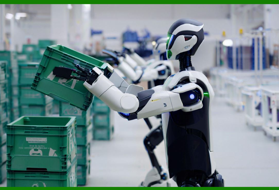
A third integration is with autonomous mobile robots that transport materials and tools. The laser guidance robot can communicate with the transport robot to request additional cable tray sections or fasteners. This reduces the time workers spend waiting for materials and improves the overall efficiency of the assembly process. |
A fourth integration is with digital twin systems. The laser guidance robot can feed data back to a digital twin of the wind turbine, allowing engineers to monitor the assembly process in real time and to identify potential issues before they become problems. |

|
8. Challenges and Limitations |
Despite its benefits, the mobile robot assistant with laser guidance is not without challenges and limitations. |
One challenge is the initial cost. The system requires a mobile base, a robotic arm or gantry, a laser projector, and a control system. The total cost can be significant, particularly for small manufacturers. However, the productivity gains often justify the investment, particularly for high-volume production. |
Another challenge is the need for calibration. The system must be calibrated for each tower section, which takes time and requires skilled personnel. This can be a barrier for manufacturers with limited technical resources. |
A third challenge is the environment. Wind turbine towers can be dusty, humid, or exposed to extreme temperatures. The laser guidance system must be designed to operate reliably in these conditions. This may require ruggedized components and environmental sealing. |
A fourth challenge is the need for training. While the system reduces the training required for cable tray assembly, it requires training for the operators who set up and maintain the system. This training must cover both the hardware and the software. |
A fifth challenge is the need for integration. The laser guidance system must be integrated with the existing manufacturing process, including the production schedule, the material handling system, and the quality control system. This integration can be complex and time-consuming. |

|
9. Future Developments |
The future of mobile robot assistants with laser guidance in wind turbine manufacturing is likely to involve several developments. |
One development is increased autonomy. Future systems may be able to navigate the tower interior without human intervention, identify the correct positions for cable trays automatically, and adjust the laser projection in real time as the tower geometry changes. |
Another development is increased collaboration. Future systems may be able to work alongside human workers more seamlessly, projecting guidance that adapts to the worker's position and movements. This could involve the use of augmented reality displays or collaborative robots that hand tools and materials to workers. |
A third development is increased integration with other systems. Future systems may be able to communicate with design software, production planning systems, and quality control systems to provide a fully integrated manufacturing solution. |
A fourth development is increased use of artificial intelligence. Future systems may be able to learn from previous assemblies, identify patterns, and optimize the assembly process. They may also be able to detect anomalies and predict potential problems before they occur. |
A fifth development is increased use of mobile robots for on-site assembly. As wind turbines are installed in increasingly remote locations, there is a growing need for robotic systems that can operate on-site. Mobile robot assistants with laser guidance could be used to guide the assembly of cable trays and other components during installation, reducing the need for skilled workers to travel to remote sites. |

|
10. Detailed Summary |
This chapter has examined the role of mobile robot assistants with laser guidance in wind turbine manufacturing, with a particular focus on cable tray assembly. The key points are as follows. |
First, wind turbine manufacturing is a demanding industry that requires the handling of very large components with high precision. Robotics has become increasingly important in this industry, performing tasks that range from welding and gelcoating to precision drilling and laser-guided assembly. |
Second, cable tray assembly is a critical but time-consuming step in wind turbine manufacturing. Traditionally performed manually, it involves measuring, marking, drilling, and fastening hundreds of meters of cable tray in the tower, nacelle, and hub. |
Third, the mobile robot assistant with laser guidance is a solution that addresses this challenge. The system projects a laser pattern onto the interior surface of the tower, indicating exactly where holes should be drilled and where cable trays should be positioned. Workers follow this guidance to perform the installation. |
Fourth, the system has been shown to reduce processing time by 37 percent, from 40 minutes to 25 minutes per tower section, without requiring manual adjustments. This translates into significant cost savings and productivity gains for wind turbine manufacturers. |
Fifth, the system offers several benefits beyond time savings, including improved accuracy, improved safety, improved consistency, reduced training time, and better documentation. |
Sixth, similar systems have been deployed in several other industries, including aerospace, shipbuilding, construction, heavy machinery, rail vehicle manufacturing, and wind turbine blade manufacturing. These applications provide valuable context and suggest opportunities for cross-sector learning. |
Seventh, the system can be integrated with other robotic systems, including automated drilling systems, automated fastening systems, autonomous mobile robots, and digital twin systems. |
Eighth, the system faces several challenges, including initial cost, calibration requirements, environmental conditions, training needs, and integration complexity. |
Ninth, the future of the system is likely to involve increased autonomy, increased collaboration, increased integration, increased use of artificial intelligence, and increased use of mobile robots for on-site assembly. |
|
In conclusion, the mobile robot assistant with laser guidance represents a significant advancement in wind turbine manufacturing. By reducing processing time, improving accuracy, and enhancing safety, it addresses many of the key challenges facing the industry. Its success in wind turbine manufacturing also demonstrates the broader potential of mobile robot assistants in other industries, particularly those that involve large structures, complex assemblies, and demanding environments. As the wind energy industry continues to grow, and as wind turbines become larger and more complex, the role of robotics in manufacturing is likely to become even more important. The mobile robot assistant with laser guidance is one example of how robotics can help meet the challenges of this rapidly evolving industry. |
 cs@easiersoft.com