From Photons to Bits: The Circuit Principles and Design Reality of Barcode Scanners |
Abstract: The barcode scanner is a ubiquitous but deceptively complex optoelectronic system. Behind the familiar 'beep' lies a chain of analog signal conditioning, mixed-signal conversion, and digital decoding that varies dramatically across scanner architectures. This article dissects the electrical structures and circuit principles of the three dominant scanner families---wand, CCD, and laser---using patent and application literature to expose the design trade-offs engineers actually face. It compares their strengths and weaknesses on metrics that matter: signal-to-noise ratio, ambient light rejection, depth of field, and power consumption. Finally, it examines where the circuitry is heading as linear barcodes give way to two-dimensional symbologies and the scanner becomes an edge-computing device rather than a simple transducer. |

|
Part I: The Universal Signal Chain and Why It Matters |
1. Every barcode scanner, regardless of the optical engine, performs the same fundamental task: convert spatial reflectance variations into a time-domain electrical signal, then decide where the edges are. |
2. The universal chain begins with a photodetector---a photodiode, a linear CCD array, or a CMOS imager---that produces a current proportional to incident light intensity. |
3. The first circuit is almost always a transimpedance amplifier (TIA), converting photocurrent to voltage while presenting a low impedance to the detector to preserve bandwidth. |
4. The TIA's feedback network sets the transimpedance gain and, critically, the bandwidth. A 1 M(Q) gain with a 1 pF feedback capacitor yields a pole at roughly 160 kHz---adequate for a 40 kHz laser scan rate but marginal for high-speed CCD clocks. |
5. Following the TIA, a high-pass filter removes the DC component. This is not cosmetic. Ambient light, whether fluorescent flicker or sunlight, manifests as a large DC pedestal that would otherwise saturate subsequent gain stages. |
6. A typical high-pass corner for a laser scanner sits around 2.6 kHz , high enough to reject fluorescent lamp modulation (100/120 Hz) and low enough to preserve barcode edge information at reasonable scan speeds. |
7. The signal then passes through a variable-gain amplifier (VGA). The VGA compensates for the enormous dynamic range of reflected light: a white label at 5 cm returns orders of magnitude more light than a dirty label at 30 cm. |
8. Automatic gain control (AGC) closes the loop around the VGA. The AGC detector is typically a peak detector or an RMS-to-DC converter feeding a comparator with hysteresis. |
9. A differentiated signal---the derivative of the received reflectance profile---is often preferred because barcode decoding ultimately cares about transitions, not absolute levels. Differentiation converts a square-ish reflectance profile into bipolar impulses at bar edges . |
10. The final analog stage is a comparator that slices the conditioned signal into a binary waveform. The comparator's threshold must adapt; a fixed threshold fails the moment illumination or label contrast changes. |
11. Hysteresis in the comparator prevents chatter when the signal hovers near the threshold, a condition common with poor print quality or specular reflections . |
|
Part II: Wand Scanners---The Minimalist Circuit |
12. The wand scanner is the simplest electrical architecture: an LED illuminator, a photodiode detector, and a single comparator, with the human operator serving as the scan engine . |
13. The LED is driven by a constant-current source, often a simple transistor current mirror. No modulation is used; the LED stays on continuously during a scan. |
14. The photodiode operates in photovoltaic or photoconductive mode. In photovoltaic mode, the TIA's virtual ground holds the diode at zero bias, minimizing dark current and noise. |
15. Because the operator moves the wand at a variable and unpredictable rate, the resulting signal has no fixed frequency content. The circuit must therefore accommodate a wide range of edge rates, from nearly DC to several kilohertz. |
16. The comparator in a wand scanner typically has a fixed threshold set by a potentiometer or a resistor divider. This works because the wand is in contact with the label; the optical path is short and stable, so contrast is predictable. |
17. The wand's weakness is not electrical but mechanical. The operator must maintain contact and a consistent sweep speed. The circuit cannot compensate for poor technique. |
18. Some wand designs add a second photodiode to monitor LED output and close a feedback loop, stabilizing illumination intensity against temperature and aging. |
19. The wand's electrical simplicity translates directly to cost and ruggedness. There is no motor to fail, no laser to degrade, and no firmware to crash. For low-volume, low-cost applications, this remains compelling. |
20. The wand's fatal limitation is depth of field. Because the LED illuminates a broad area and the photodiode integrates all returned light, there is no spatial resolution mechanism other than the fixed aperture. |
|
Part III: CCD Scanners---Spatial Parallelism in Silicon |
21. The CCD scanner replaces the single photodiode with a linear array of hundreds or thousands of photosite elements, each accumulating charge proportional to local illumination over an integration period . |
22. The electrical architecture changes fundamentally. Instead of a continuous analog signal, the CCD produces a sequence of charge packets that are shifted out through a charge-to-voltage converter, typically a floating diffusion amplifier. |
23. The CCD's clock driver is a critical analog circuit. It must generate multi-phase clock signals (often three or four phases) with precise overlap and amplitude, typically 5 to 12 volts, to transfer charge efficiently without lag. |
24. A correlated double sampling (CDS) circuit follows the output amplifier. CDS subtracts the reset noise (kTC noise) from each pixel by sampling the floating diffusion voltage both before and after charge transfer. |
25. Without CDS, the reset noise of the sense node would dominate the pixel signal for low-light conditions, making the CCD unusable at the scan rates required for handheld operation. |
26. The CDS output feeds an analog-to-digital converter, typically 8 to 12 bits at a rate of several megasamples per second. The ADC's sample clock must be phase-locked to the CCD transfer clock to avoid sampling artifacts. |
27. Illumination for a CCD scanner is provided by a bank of LEDs, often red (660 nm) or white, arranged symmetrically around the imaging lens. The LED driver is usually a switched-mode current source to minimize power dissipation. |
28. Because the CCD integrates charge over a defined window, the LED illumination can be pulsed synchronously with the integration period. This improves ambient light rejection: light from fluorescent fixtures that falls between integration windows is discarded. |
29. The CCD's fundamental electrical advantage is parallelism. All pixels are exposed simultaneously, so the scan time is determined by the integration period and the readout clock, not by mechanical motion. |
30. The CCD's fundamental limitation is that it is a snapshot device. The entire barcode must fit within the array's field of view at one instant. For a 4-inch-wide array, barcodes longer than about 4 inches are unreadable . |
31. Depth of field for a CCD scanner is set by the lens aperture and focal length. A typical fixed-focus design yields less than one inch of usable range, which is why CCD scanners are often contact devices . |
32. The CCD's charge transfer efficiency (CTE) degrades with radiation and overvoltage stress. A CTE of 0.99999 per transfer sounds impressive until one realizes that a 2048-element array requires over 4000 transfers, leaving only 96% of the original charge. |
33. Modern CCD scanners increasingly use CMOS linear arrays instead. CMOS active-pixel sensors integrate the charge-to-voltage conversion inside each pixel, eliminating the CTE problem and allowing lower supply voltages. |
|
Part IV: Laser Scanners---The Flying Spot and Its Demands |
34. The laser scanner's electrical architecture is defined by the need to synchronize a photodetector with a moving beam. The photodetector sees a time-varying signal only because the beam sweeps across the barcode; the circuit must recover the spatial pattern from this temporal waveform. |
35. The laser diode is driven by a pulsed current source, not a continuous one. Pulsing serves two purposes: it reduces average power dissipation (important for battery-operated guns) and it enables synchronous demodulation for ambient light rejection . |
36. In a representative design, the laser is pulsed at 500 kHz with a 50% duty cycle. The photodetector signal is multiplied by +1 when the laser is on and 1 when it is off . |
37. The synchronous demodulator's output contains the barcode signal plus ambient light during the 'on' phase, and ambient light alone during the 'off' phase. Averaging over a full cycle cancels the ambient term, provided the ambient light is constant over the cycle . |
38. The demodulator's gain ratio must match the duty cycle. For a 20% duty cycle, the 'on' gain is 4 and the 'off' gain is 1, so that the ambient contributions cancel exactly . |
39. This technique is elegant but fragile. If the ambient light changes rapidly within a cycle---as it does under fluorescent lamps with magnetic ballasts, which modulate at twice the line frequency---the cancellation is incomplete. |
40. A derivative amplifier follows the demodulator, providing gain in the barcode signal band (up to roughly 30 kHz for typical scan speeds) and attenuation at the carrier frequency (500 kHz) . |
41. The derivative amplifier is followed by a bandpass filter, typically a two-pole active filter with a center frequency in the tens of kilohertz and a Q of 1 to 2. |
42. The filter's output is digitized by a comparator, but the comparator's threshold is not fixed. An AGC loop senses the peak-to-peak signal amplitude and adjusts the VGA gain to keep the comparator input within a usable range. |
43. The scanning mirror is driven by a resonant motor, typically operating at 50 Hz . The motor drive circuit must track the resonant frequency, which shifts with temperature and aging, to maintain scan amplitude. |
44. A phase-locked loop (PLL) or a simpler zero-crossing detector on the motor's back-EMF signal provides the synchronization reference for the scan. |
45. The motor drive itself is often a bidirectional H-bridge for a moving-coil actuator. The current waveform is sinusoidal, synthesized by PWM at a frequency well above the mechanical resonance. |
46. The laser scanner's optical feedback path includes a monitor photodiode inside the laser package. A closed-loop power control circuit compares the monitor current to a reference and adjusts the laser drive current to maintain constant output power . |
47. Without this loop, the laser's threshold current would shift with temperature (roughly 1% per C for typical VCSELs), causing output power to vary by tens of percent over a handheld unit's operating range. |
48. The laser scanner's great electrical advantage is its signal-to-noise ratio. A 1 mW laser concentrated into a small spot delivers far more photons per resolvable element than an LED floodlight, so the TIA can use lower gain and wider bandwidth. |
49. The laser scanner's great electrical disadvantage is speckle noise. Coherent light reflected from a rough surface produces a random interference pattern that the photodetector integrates into amplitude noise, imposing a fundamental limit on SNR that no amount of circuit cleverness can eliminate. |
50. Speckle noise is mitigated by aperture averaging (a larger detector area), wavelength diversity (using multiple laser wavelengths), or spatial diversity (multiple detectors), each of which adds cost and complexity. |

|
Part V: Decoding Circuits and the Digital Boundary |
51. The digitized barcode signal---a serial bitstream of bar/space widths---enters the decoder, which is now almost universally a microcontroller or a dedicated DSP. |
52. The first digital task is edge detection. The comparator output is sampled at a rate well above the maximum edge rate, and a state machine detects transitions. |
53. Edge-to-edge intervals are measured with a hardware timer. The timer resolution sets the fundamental limit on narrow-bar discrimination; a 1 us resolution is adequate for X-dimensions down to about 5 mils at typical scan speeds. |
54. The interval sequence is then matched against the symbology's encoding rules. For UPC/EAN, the decoder checks the guard patterns, computes the check digit, and verifies the quiet zones. |
55. The decoder must handle the reality that scan lines are not perfectly perpendicular to the bars. A skewed scan stretches the apparent widths, but the ratios between adjacent elements remain approximately preserved. |
56. For laser scanners, the decoder often receives multiple scan lines from successive sweeps and can vote across them. A character decoded consistently across three sweeps is almost certainly correct. |
57. The voting logic must account for the fact that different sweeps may illuminate different portions of the barcode, especially if the label is curved or the scan angle varies. |
58. A 'paper detector' circuit is sometimes included to distinguish a barcode label from a blank surface. It examines the demodulated signal for the presence of high-frequency pulses characteristic of bar edges, and reduces LED or laser duty cycle when no label is present, saving power . |
59. The decoder's output interface---USB, RS-232, or a proprietary keyboard wedge---is electrically mundane but practically critical. USB enumeration must occur before the first scan, or the host will miss the data. |
60. ESD protection on the interface lines is not optional. A handheld scanner accumulates charge from the user and the environment, and a discharge through the USB data lines can destroy the transceiver. |
|
Part VI: Comparative Assessment |
61. On cost, the wand wins decisively. Its bill of materials is dominated by the photodiode, LED, and comparator. A CCD scanner adds the array, clock drivers, CDS, and ADC. A laser scanner adds the laser diode, monitor photodiode, scanning motor, and motor drive. |
62. On depth of field, the laser scanner dominates. A typical handheld laser gun reads from contact to 30 cm or more. The CCD scanner is limited to about 2.5 cm. The wand is a contact-only device . |
63. On ambient light immunity, the synchronous demodulation of the laser scanner provides the best rejection, followed by the CCD's synchronous integration, with the wand's continuous illumination being the most vulnerable. |
64. On barcode quality tolerance, the laser scanner's flying spot can often read damaged labels by finding a clean scan line through the damage. The CCD integrates across the entire label width, so a defect anywhere in the field of view corrupts the entire scan. |
65. On power consumption, the wand is lowest (tens of milliwatts), the CCD is intermediate (hundreds of milliwatts during scan), and the laser scanner is highest (laser plus motor, often over 1 W during scan). |
66. On reliability, the wand has no moving parts and no laser to degrade. The CCD has no moving parts but the array is sensitive to ESD and radiation. The laser scanner's motor bearings and laser facet are the weak points. |
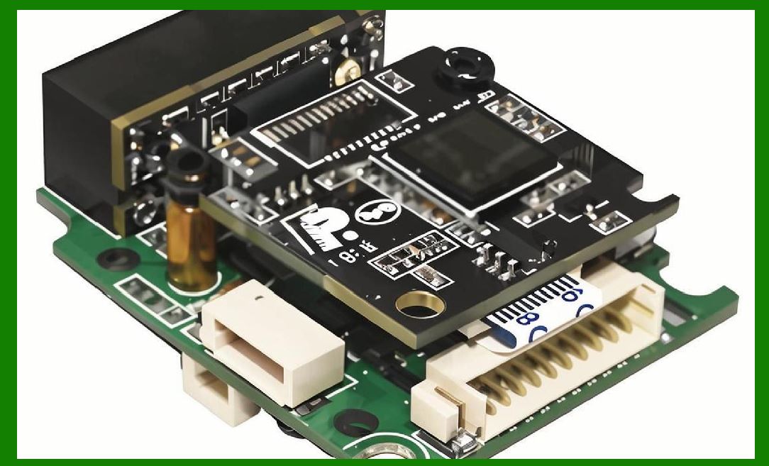
67. On two-dimensional symbology capability, none of the linear scanners is adequate. A laser scanner sweeps a line, not an area; a CCD linear array captures a line, not an area; a wand captures a point trajectory, not an image. Reading a QR code requires a 2D imager. |
|
Part VII: The Future Is Computational |
68. The migration from linear to 2D symbologies is not a market preference; it is a regulatory and operational necessity. GS1's 'Sunrise 2027' initiative and the subsequent transition to QR Code powered by GS1 and GS1 DataMatrix require scanners that can capture and decode matrix codes . |
69. The electrical architecture of a 2D imager is fundamentally different. It uses a CMOS area sensor---essentially a camera---with row and column addressing, per-pixel amplifiers, and often on-chip ADCs. |
70. The 2D imager's signal chain looks less like a barcode scanner and more like a machine vision system: global or rolling shutter, correlated double sampling at the column level, and a digital interface (MIPI CSI-2 or parallel) to an image signal processor. |
71. The illumination system becomes an array of high-brightness LEDs with diffusers to provide uniform flood illumination across the field of view, often with pulsed operation synchronized to the exposure. |
72. The 'decoder' becomes a full image-processing pipeline: adaptive thresholding, connected-component analysis, perspective correction, and then symbology-specific decoding. |
73. This computational load is increasingly handled by a dedicated vision processor or an FPGA, not a general-purpose MCU. The power budget shifts from the analog front end to the digital back end. |
74. Artificial intelligence is entering the pipeline at the edge. Neural network accelerators can perform barcode localization and even decoding from degraded images where classical algorithms fail---torn labels, extreme perspective, low contrast . |
75. The analog front end does not disappear, but its requirements change. Dynamic range becomes more important than bandwidth: a 2D imager must capture both bright specular highlights and shadowed recesses in the same frame. |
76. High dynamic range (HDR) imaging, using multiple exposures per frame or dual-conversion-gain pixels, is becoming standard in 2D scanners. |
77. The laser scanner will not vanish entirely. For high-speed fixed-position sortation---conveyor belts moving at meters per second---the flying-spot laser remains unmatched in scan rate and depth of field. |
78. But even there, the trend is toward laser-based 2D profiling, where the laser line is imaged by an area sensor and the profile is extracted computationally, enabling the scanner to read codes on arbitrarily oriented packages. |
79. The wand scanner will survive in the lowest-cost, lowest-volume niches---library checkout, simple inventory counts---where its electrical simplicity and mechanical robustness outweigh its ergonomic limitations. |
80. The overarching trend is clear: the barcode scanner is becoming a computational imaging device. The circuit designer's job is shifting from optimizing a 40 kHz analog filter to specifying an image sensor's dynamic range and a processor's TOPS. The beep remains, but the electrons behind it are increasingly digital. |
 cs@easiersoft.com