Article Summary |
Electrostatic discharge protection on interface lines is not an optional refinement but a fundamental survival requirement for handheld barcode scanners. This article explains why the USB data lines of a handheld scanner represent a uniquely vulnerable pathway for electrostatic energy, how that energy destroys the transceiver IC, and what circuit-level measures prevent it. Drawing on real-world applications across warehousing, retail, healthcare, manufacturing, and field services, the discussion illustrates that ESD protection is not a single component choice but a system-level discipline involving placement, grounding, and an understanding of how the human body interacts with the device throughout its working life. |
|
1. The Physical Reality of a Handheld Device |
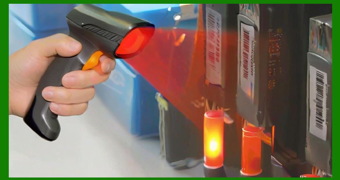
A handheld barcode scanner is, from an electrostatic perspective, a charge collector that happens to read barcodes. The user lifts it from a cradle, grips it with a hand that may have accumulated several kilovolts of potential from walking across a synthetic carpet or sliding across a fabric-covered car seat, and points it at a label. Every one of these actions is an opportunity for charge transfer. The scanner's plastic housing insulates the user's hand from the internal circuitry during normal operation, but the moment a cable is plugged in or a metal connector shell is touched, a path exists. If that path runs through the USB data lines, the transceiver that translates the scanner's digital output into USB protocol packets is directly in the firing line. |
The problem is not hypothetical or confined to laboratory conditions. Handheld scanners are used in environments where static charge is generated constantly: dry warehouse air in winter, the friction of cardboard boxes against plastic pallets, the movement of a worker wearing a synthetic uniform. The device accumulates charge from the user and the environment, and a discharge through the USB data lines can destroy the transceiver. This is the sentence that anchors the entire discussion. It states a causal chain that is short and brutal: charge accumulates, discharge occurs, the transceiver dies. |
What makes this particularly insidious is that the failure is not always immediate or obvious. A transceiver that has been weakened by a discharge may continue to function for weeks before failing intermittently, producing corrupted data that the host interprets as a misread barcode. In a retail setting, a misread might mean a customer is charged the wrong price. In a hospital, a misread medication barcode could have consequences that extend far beyond a customer service complaint. The ESD event leaves a latent defect, and the defect surfaces at the worst possible moment. |

|
2. How the Charge Builds and Where It Goes |
Understanding the accumulation side of the equation is essential because it explains why the USB interface is the preferred path for destruction. The human body acts as a capacitor with a capacitance of roughly one hundred to two hundred picofarads, and in a dry environment, walking across a carpet can charge that capacitance to several kilovolts. When the user picks up the scanner, the device and the user reach the same potential. No current flows because there is no potential difference. The trouble begins when the scanner is connected to a host device that is referenced to earth ground, such as a point-of-sale terminal or a workstation. |
At the moment of connection, the scanner's potential equalizes with the host's ground reference through whatever conductive path is available. The USB cable's shield and the data lines provide that path. If the user is still holding the scanner, the charge stored on the user's body can flow through the scanner's internal ground plane, across the printed circuit board, and into the USB connector. The data lines, being directly connected to the transceiver's input and output structures, experience a transient voltage that can rise to thousands of volts in a few nanoseconds. The transceiver's semiconductor structures are designed to handle a few volts of signal swing, not a multi-kilovolt pulse. |
The environment contributes its own charge. In a warehouse, the simple act of walking across a concrete floor coated with epoxy can generate triboelectric charge on the soles of shoes. The scanner, resting in a holster or placed on a shelf, can accumulate charge through induction or direct contact with charged surfaces. When a worker picks it up and plugs in the charging cable or the USB data cable, the accumulated charge finds its way to ground through the most sensitive semiconductor junctions available. The transceiver, with its tiny gate oxides and shallow junctions, is the weakest link in that chain. |

|
3. The Transceiver as a Sacrificial Element |
The USB transceiver is not designed to be a protection device. It is designed to transmit and receive differential signals at speeds that, for USB 2.0 Full Speed, reach twelve megabits per second, and for High Speed, reach four hundred eighty megabits per second. The input and output structures are optimized for signal integrity, not for surge absorption. The gate oxide of the transistors in the transceiver's receiver front end may be only a few nanometers thick. A voltage transient that exceeds the oxide's breakdown strength by even a modest margin creates a permanent short or a leakage path that degrades performance. |
The transceiver's output drivers are similarly vulnerable. A discharge event can forward-bias parasitic structures within the driver circuit, causing a latch-up condition in which a low-resistance path forms between the power supply and ground. The current that flows through this path can be sufficient to melt the aluminum or copper traces that connect the driver to the bond pads. Even if the device survives the initial event, the metal migration and junction damage that occur during a partial latch-up can reduce the device's lifetime from decades to months. |
What makes the situation worse is that the transceiver is often integrated into a larger system-on-chip or a companion controller that handles multiple functions. When the transceiver is destroyed, the entire chip may become unusable, requiring the replacement of the main board. In a handheld scanner, the main board is often the most expensive single component after the scan engine itself. A single discharge event, lasting perhaps a few tens of nanoseconds, can convert a functioning device into a repair ticket. |

|
4. The Warehouse and Logistics Environment |
The warehouse is the canonical environment for barcode scanner ESD problems, and it provides a clear illustration of why protection is not optional. A typical distribution center operates with relative humidity that can fall below thirty percent in winter, especially in climates where heating systems dry the indoor air. At these humidity levels, charge does not bleed off surfaces the way it does in more humid conditions. A worker who walks from a loading dock to a picking station may accumulate a potential of several kilovolts simply by moving through the space. |
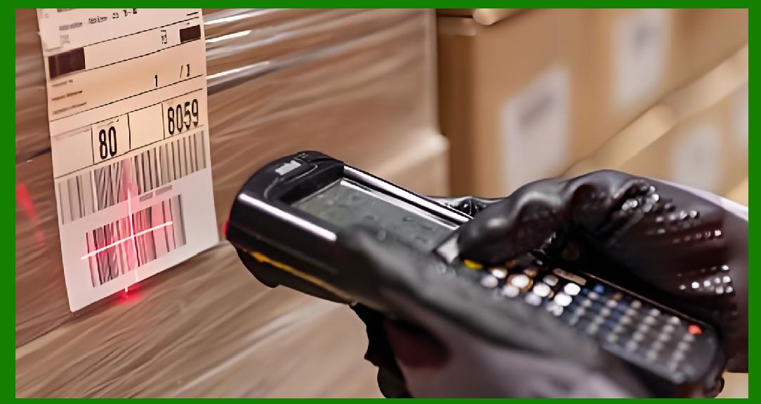
The scanner in this environment is subjected to a cyclic pattern of use and storage. It is picked up, used to scan dozens of labels, placed back in a holster or on a shelf, and then picked up again. Each pick-up and put-down cycle involves contact with the user's hand, the holster material, and whatever surface the scanner rests on. If the scanner is a corded model, the USB cable is plugged and unplugged multiple times per shift as workers move between stations or as the scanner is transferred between vehicles. Each plug and unplug event is a potential discharge path. |
A specific failure mode observed in warehouse settings is the 'winter failure spike.' Devices that have operated without incident through the humid summer months begin to fail at an elevated rate when the heating season begins. The failures are often attributed to 'bad batches' or 'manufacturing defects,' but the root cause is the seasonal change in humidity. The same scanner design that passed ESD testing at the factory in July encounters a fundamentally different electrostatic environment in January. The protection scheme must be designed for the worst-case environment, not the average one. |
The warehouse also presents a grounding challenge that is often overlooked. The scanner may be connected to a host device that is powered from a circuit with a different ground potential than the floor or the shelving. When the user touches the scanner while standing on a floor that is at a different potential, a discharge can occur through the user's body and into the scanner's circuitry. The USB cable's ground conductor, if it is the only path between the scanner and the host, carries the discharge current. The data lines, which run parallel to the ground conductor, are inductively coupled to the transient and experience a voltage spike even if they are not directly contacted. |

|
5. Retail and Point-of-Sale Applications |
The retail checkout lane presents a different set of conditions that still lead to the same conclusion about interface protection. The scanner in a supermarket or department store is typically a fixed or semi-fixed device, but it is still handled by the cashier and by customers who may pick it up to scan a heavy item. The checkout counter is often constructed with a metal frame that is connected to earth ground for safety reasons. The scanner's USB cable runs from the scanner to the point-of-sale terminal, which is also grounded. |
The customer who picks up the scanner to scan a bulky item may be carrying a static charge acquired from walking through the store. The floor in a retail environment is often carpeted or covered with a synthetic mat, both of which are charge-generating surfaces. When the customer's hand contacts the scanner's metal trigger or the scan window bezel, the charge flows into the scanner. If the scanner's housing is not properly grounded to the USB shield, the charge may preferentially flow through the internal circuitry to reach the ground path provided by the USB cable. |
A less obvious but equally important retail scenario involves the interaction between the scanner and the checkout counter itself. Many checkout counters have a metal surface or a metal edge that the scanner rests on between scans. If the counter is grounded and the scanner has accumulated charge, the moment of contact between the scanner and the counter is a discharge event. The discharge current may flow through the scanner's internal ground plane and couple into the USB data lines through the mutual inductance of the cable's conductors. The transceiver sees a transient that is not a direct contact discharge but is nonetheless sufficient to cause damage over time. |
The cumulative effect in a high-volume retail environment is significant. A single checkout lane may process hundreds of transactions per hour, and each transaction involves at least one scanner interaction. Over the course of a year, the scanner experiences hundreds of thousands of contact events, each with a small probability of being an ESD event of sufficient energy to cause damage. The protection scheme must be robust enough to handle the cumulative stress, not just a single event. |

|
6. Healthcare and Clinical Settings |
Hospitals and clinics introduce a dimension that elevates ESD protection from a reliability concern to a patient safety issue. Barcode scanners in healthcare are used for medication administration, specimen tracking, and patient identification. A scanner that fails in the middle of a medication round can delay treatment. A scanner that produces corrupted data can lead to a misidentified specimen or a medication error. |
The electrostatic environment in a hospital is shaped by the extensive use of synthetic materials: vinyl flooring, plastic wall coverings, disposable gowns and drapes, and the ubiquitous nitrile gloves. A nurse wearing nitrile gloves and walking across a vinyl floor can accumulate a substantial charge. The gloves themselves are often the charge carrier, and the act of removing a glove or adjusting it can generate a discharge. When the nurse picks up the scanner to scan a patient wristband, the charge transfers to the scanner. |
The USB interface in a healthcare setting is often connected to a mobile cart or a wall-mounted terminal. These hosts are typically powered from the facility's electrical system, which is grounded but may have different ground potentials at different locations within the building. A scanner that is moved from one room to another, or from one cart to another, may experience a potential difference between its accumulated charge and the host's ground reference at the moment of connection. |
The consequences of a transceiver failure in this context extend beyond the cost of repair. A scanner that fails during a medication administration round may force the nurse to revert to manual verification, which introduces its own error pathways. A scanner that produces intermittent misreads may cause a specimen to be labeled incorrectly, with downstream consequences for diagnosis and treatment. The ESD protection on the USB lines is, in this light, not merely a circuit design detail but a component of the device's clinical safety profile. |

|
7. Manufacturing and Industrial Settings |
The factory floor is an environment where ESD is a recognized hazard, but the recognition is often focused on the protection of the product being manufactured rather than the tools used to track it. In an electronics assembly plant, for example, the entire production area may be equipped with grounded mats, ionizing fans, and wrist straps for the operators. The barcode scanner used to track work-in-progress through the line is, paradoxically, one of the few devices in the area that may not receive the same level of ESD care. |
The scanner in a manufacturing environment is often mounted on a fixture or a robot arm, or it is used by an operator who is wearing a wrist strap that is connected to a grounded workbench. The wrist strap protects the product being assembled, but it also provides a low-impedance path from the operator's body to ground. If the operator touches the scanner while wearing the wrist strap, any charge on the scanner can flow through the operator to ground. The USB cable connecting the scanner to the host is a parallel path, and the current division between the two paths depends on their relative impedances. |
In heavy manufacturing, such as automotive assembly, the scanner may be exposed to vibration, temperature extremes, and the presence of metal particles in the air. These conditions stress the connector and the cable, creating opportunities for intermittent contact and for the degradation of the ESD protection components themselves. A transient voltage suppressor that has absorbed many small discharges may gradually lose its clamping capability, leaving the transceiver exposed to the next event. The protection scheme must account for the aging of the protection components, not just their initial performance. |
The industrial environment also introduces the possibility of electrical overstress from sources other than human body discharge. A scanner connected to a host that shares a power circuit with heavy machinery may experience voltage transients on the USB cable's power and ground conductors. These transients can couple into the data lines and reach the transceiver even if no human contact occurs. The protection network must handle both the fast, high-voltage ESD event and the slower, lower-voltage surge that originates from the electrical system. |

|
8. Field Service and Mobile Applications |
The handheld scanner that is carried from location to location by a field service technician, a delivery driver, or a utility meter reader faces the most varied electrostatic environment of all. The device is exposed to the interior of a vehicle, the outdoors, customer premises, and the transition between them. Each transition involves a change in the local electrostatic potential, and each change is an opportunity for a discharge. |
A delivery driver who carries a scanner in a holster on a belt and steps out of a vehicle after driving for an hour has accumulated charge from the vehicle's upholstery and from the friction of the seatbelt and clothing. The scanner, resting against the driver's body, is at the same potential. When the driver reaches for the scanner and simultaneously touches a metal door handle or a mailbox, the discharge path may run through the scanner's circuitry if the scanner is the most convenient conductive path between the driver and the grounded object. |
The USB interface in a mobile application is often used for charging as well as data transfer. The charging cable may be plugged into a vehicle's twelve-volt accessory socket through a USB adapter, or into a portable power bank. The ground reference of the vehicle's electrical system is the chassis, which is connected to the tires and, through them, to the road surface. The ground reference of the power bank is its internal battery negative terminal, which is floating with respect to earth. When the scanner is connected to one of these hosts while the user is in contact with a grounded object, the potential difference between the host's ground and the user's ground can drive current through the scanner's USB interface. |
The field service environment also exposes the connector itself to wear and contamination. Dust, moisture, and repeated insertion and removal degrade the connector's contacts and the integrity of the shield connection. A connector with a partially compromised shield provides a less effective path for ESD current to bypass the data lines, increasing the stress on the transceiver. The protection scheme must be designed with the assumption that the connector will not remain pristine throughout the device's service life. |
|
9. The Protection Component and Its Limitations |
The transient voltage suppressor, or TVS diode, is the component most commonly used to protect the USB data lines. It is placed between the data line and ground, ideally as close to the connector as possible. Under normal operating conditions, the TVS presents a high impedance to the signal and does not affect data transmission. When a transient voltage exceeds the device's breakdown threshold, the TVS transitions to a low-impedance state and shunts the transient current to ground, clamping the voltage at the data line to a level that the transceiver can survive. |
The TVS is not a perfect solution. It has a finite response time, typically measured in fractions of a nanosecond, and during that response time, the leading edge of the ESD pulse can reach the transceiver. The TVS also has a clamping voltage that is not zero; even when it is fully conducting, the voltage across the data line may rise to several volts or more, depending on the current through the device and its dynamic resistance. If the transceiver's absolute maximum rating is lower than the TVS's clamping voltage under the actual discharge current, the transceiver remains at risk. |
The capacitance of the TVS is another critical parameter. USB 2.0 High Speed signals at four hundred eighty megabits per second are sensitive to capacitive loading. A TVS with a capacitance of a few picofarads is generally acceptable for USB 2.0, but the same device would be unsuitable for the SuperSpeed lanes of USB 3.x, which require capacitances below one picofarad. The choice of protection component is therefore coupled to the choice of interface speed, and a scanner that migrates from USB 2.0 to USB 3.x requires a corresponding change in the protection scheme. |
The placement of the TVS is as important as its specifications. A TVS placed on the far side of the connector, close to the transceiver, allows the ESD current to flow through the intervening trace before it is shunted. The voltage drop across that trace, multiplied by the transient current, appears at the transceiver's input. The inductance of the trace and of the ground return path can cause the clamping voltage at the transceiver to be significantly higher than the voltage measured at the TVS terminals. The protection component must be placed at the point where the ESD energy enters the board, and its ground connection must be a low-impedance path to the board's ground plane. |

|
10. Beyond the Component: Layout and Grounding |
The effectiveness of an ESD protection scheme depends on the physical layout of the printed circuit board as much as on the choice of components. The ESD current, once it enters the board through the connector, must find a path to ground that does not pass through sensitive circuitry. If the ground path is long or inductive, the voltage developed across it during the discharge can couple into other parts of the circuit, causing disruption even if the transceiver itself survives. |
The connector's metal shell, if it is present, should be connected to the board's ground plane through a low-impedance path that is separate from the signal ground return. This connection provides a preferred path for ESD current that bypasses the data lines entirely. In many connector designs, the shell is connected to the shield of the cable, and the shield is connected to the host's chassis ground. The shield therefore provides a parallel path for the discharge, and the proportion of the current that flows through the shield versus the data lines depends on the relative impedances of the two paths. |
The ground plane beneath the connector and the TVS components should be solid and continuous, with multiple vias connecting the top and bottom layers. A ground plane that is fragmented or that relies on a single via to connect to the main ground can develop a significant voltage during a discharge, and that voltage can appear across the TVS and the transceiver. The layout should treat the ESD ground path as a high-current path, even though the current flows for only a few nanoseconds. The inductance of the path, not just its resistance, determines the voltage developed. |
The data lines themselves should be routed to minimize their exposure to the ESD current path. They should not run parallel to the ground return path for any significant distance, because the magnetic field of the discharge current can couple into the data lines and induce a voltage spike. They should be routed away from the board edge and away from the connector's mounting hardware. These layout considerations are not optional refinements; they are the difference between a protection scheme that works and one that merely provides a false sense of security. |

|
11. The Role of the Enclosure and the User |
The device's enclosure and the way the user interacts with it are part of the ESD protection system, even though they are not circuit components. A metal enclosure that is connected to the circuit ground provides a Faraday cage effect and a preferred path for discharge current. A plastic enclosure with no conductive coating offers no such path, and the discharge current must find its way through the internal circuitry. Many handheld scanners use a plastic housing with a metallic coating on the inside surface, or with metal inserts around the scan window and the trigger, to provide a controlled path for ESD current. |
The trigger is a particularly sensitive point of interaction. The user's finger, which may be the source of the charge, presses the trigger hundreds or thousands of times per shift. The trigger mechanism is typically a plastic button that actuates a switch on the circuit board. If the button is not grounded or if the switch is not protected, the charge on the user's finger can discharge directly into the switch contacts and from there into the scanner's microcontroller. The switch and its associated circuitry must be protected with the same care as the USB interface. |
The scan window is another entry point. In a laser scanner, the window is transparent to the laser wavelength but may accumulate charge from the air and from contact with objects being scanned. The window is often made of glass or polycarbonate, both of which can hold a static charge. If the window is not connected to a controlled ground path, the charge can discharge through the optical sensor and its associated circuitry. The protection scheme must extend beyond the electrical interface to the entire user-accessible surface of the device. |

|
12. Testing and Validation |
The ESD protection scheme must be validated under conditions that approximate the real-world environment. The IEC 61000-4-2 standard defines the test waveforms and levels that are most relevant to system-level ESD. The standard specifies contact discharge and air discharge tests at levels up to eight kilovolts for contact and fifteen kilovolts for air, though some applications require higher levels. The test simulates the discharge from a human body that has been charged to a specified voltage, with a waveform that has a fast rising edge and a slower decay. |
A scanner that passes the IEC test at the specified level is not necessarily immune to field failures, because the test is a simplified model of a complex phenomenon. The test is performed with the device in a defined configuration, typically on a grounded table, with the discharge applied to specific points. In the field, the discharge can occur at any point on the device, through any path, with any combination of charge and discharge impedance. The test provides a minimum confidence level, not a guarantee. |
The test should be performed on the complete device, not just the circuit board, because the enclosure and the user interface are part of the ESD path. The device should be tested in the configuration in which it is used: with the USB cable connected to a host that represents the actual application, with the trigger and the scan window accessible, and with the device held in a manner that approximates the user's grip. A test that applies the discharge only to the connector pins does not capture the full range of real-world events. |
The results of the test should be evaluated not only for hard failures, in which the device stops working, but also for soft failures, in which the device continues to function but produces errors or requires a reset. A transceiver that is partially damaged may pass a functional test immediately after the ESD event but fail hours or days later. The test protocol should include a post-test functional check and, ideally, a burn-in period to detect latent damage. |

|
13. The Economics of Protection |
The cost of adding a TVS diode to a USB data line is measured in cents. The cost of a field failure is measured in dollars, in lost productivity, in customer dissatisfaction, and in the administrative overhead of processing returns and repairs. For a device that is manufactured in quantities of tens or hundreds of thousands, the difference between a protection scheme that works and one that does not is the difference between a profitable product and a warranty liability that consumes the product's margin. |
The economics become even more compelling when the cost of the host device is considered. A handheld scanner is often connected to a point-of-sale terminal, a mobile cart, or an industrial controller that costs far more than the scanner itself. An ESD event that damages the host's USB port is a more expensive failure than one that damages the scanner. The protection on the scanner's interface lines is therefore not just protecting the scanner; it is protecting the entire system of which the scanner is a part. |
There is also a hidden cost in the design cycle. A product that fails ESD testing late in development requires redesign, requalification, and schedule adjustment. The cost of adding protection components and adjusting the layout early in the design is trivial compared to the cost of discovering the problem after the tooling has been cut and the production line has been qualified. The sentence that opened this article, that ESD protection is not optional, is an economic statement as much as an engineering one. |

|
Detailed Summary |
The protection of USB interface lines against electrostatic discharge is a non-negotiable requirement for any handheld barcode scanner. The physical reality of the device, which is held in the user's hand and connected to grounded hosts, creates a continuous pathway for charge to enter the circuitry. The transceiver, optimized for signal integrity rather than surge absorption, is the weakest link in that pathway and the most likely component to be destroyed. The environments in which scanners are used, from warehouses with low winter humidity to retail checkout lanes to hospital wards to field service vehicles, each present a distinctive pattern of charge generation and discharge that stresses the interface in different ways. The protection component, typically a transient voltage suppressor, must be selected for its clamping voltage, its capacitance, and its response time, and it must be placed at the point where the ESD energy enters the board. The layout of the ground path and the routing of the data lines determine whether the protection component can do its job. The enclosure and the user interface are part of the protection system, not separate from it. Testing to IEC 61000-4-2 provides a minimum confidence level but does not replace an understanding of the real-world environment. The cost of protection is trivial compared to the cost of failure, and the failure is not a matter of if but of when. The scanner that reads a barcode is also a device that collects charge, and the circuit designer who ignores this dual identity does so at the product's peril. |
 cs@easiersoft.com