Part V: Decoding Circuits and the Digital Boundary | Chapter 54: From Interval Sequences to Meaning: The Last Mile of Symbology Matching | Chapter Summary: After the scanner front end completes photoelectric conversion and digitization, what the decoder holds in its hands is nothing more than a string of time intervals or widths measured in microseconds or pixels. These numbers are meaningless in themselves until they are placed within the rule framework of a specific symbology and tested. This chapter traces this critical step: how interval sequences are matched into valid characters and symbols, how verification mechanisms intercept errors, and how this process presents radically different real-world faces across such diverse industries as retail, healthcare, manufacturing, logistics, and aviation. We will see that the 'last mile' of decoding is far from mere algorithm execution; it must make judgments in the crevices between noise, motion, wear, and human error, and the cost of each judgment can differ dramatically across industries. | 
| 1. What an Interval Sequence Is, and Why It Needs to Be 'Matched' | An interval sequence is the scanner's digitized record of bar and space widths, but it is only a string of relative values that must be translated into the characters defined by a symbology. | When a scanner completes a single scan line across a barcode symbol, the output of the digitizing circuit is a string of interval sequences expressed in counting units. Each 'interval' corresponds to the duration or pixel count from one black-to-white transition to the next white-to-black transition. In laser scanners, these values are recorded as clock pulse counts; in image-based scanners, they are stored as pixel widths or multiples of the module width. Either way, the raw data takes the form of an ordered set of numbers describing the rhythm of light and dark alternation along the scan line. | The problem is that these numbers do not directly tell you 'this is the letter A' or 'this is the digit 7.' They only tell you: the first dark segment lasted a certain number of units, the first light segment lasted a certain number of units, the second dark segment lasted yet another number of units, and so on. Each symbology -- whether UPC/EAN, Code 128, Code 39, or GS1 DataBar -- defines its own set of encoding rules specifying which combinations of interval widths correspond to which characters, and which combinations constitute start patterns, stop patterns, or check digits. The decoder's task is to pass this meaningless string of numbers through the sieve of rules again and again until some legitimate interpretation emerges, or until it gives up entirely. | The core challenge of this process lies in 'relativity.' Printed barcodes in the physical world are never perfect. The heating elements of a thermal printer may have slight deviations, the label material may be slightly stretched during peeling, the scan angle may introduce perspective distortion in effective module width, and motion blur may cause edge determinations to waver between adjacent pixels. The decoder cannot demand that interval sequences exactly equal theoretical values; it must learn to work within tolerance ranges. Different symbologies specify different tolerances, but the basic principle is consistent: compare measured interval widths with other intervals within the same character, using ratios rather than absolute values to make judgments. | Therefore, the word 'matching' here carries a meaning far richer than its literal sense of 'looking up a correspondence.' It means the decoder must weigh multiple candidate interpretations, must maintain reasonable judgment when certain intervals deviate from expectations due to noise, and must attempt to recover complete information from fragments when a scan line covers only part of a symbol. When all these efforts fail, the decoder must also know when to give up rather than forcibly output an erroneous result. This ability to 'know when to say no' is precisely one of the most subtle and critical aspects of decoding circuit design. | 
| 2. UPC/EAN Guard Patterns: How Start and Stop Patterns Serve as Decoding Anchors | The guard patterns of UPC/EAN symbols provide a fixed interval rhythm that enables the decoder to lock onto symbol boundaries amid uncertain scan data. | In the UPC and EAN symbologies, the starting point of decoding is not an arbitrary character. Every legitimate symbol begins with a specific guard pattern and ends with a corresponding guard pattern. For standard UPC-A and EAN-13 symbols, the left guard pattern consists of three thin bars whose interval rhythm is unique within the entire symbol: thin, thin, thin, but with an order and relative positioning of bar-space alternation unlike any combination found in data characters. After receiving the interval sequence, the decoder first scans this sequence looking for a rhythmic fragment matching the guard pattern. Once found, it knows: 'The symbol starts here, and the following intervals should fall into the left-side data character encoding table in groups of six units.' | The role of guard patterns is not merely to mark the starting point. Because they appear in every scan at fixed positions, guard patterns provide the decoder with a calibration reference. If the scan speed changes slightly during the scanning process -- almost inevitable in handheld scanners -- the variation in guard pattern interval widths can be used to estimate the degree of this drift, thereby adjusting the interpretation of subsequent data character intervals accordingly. The right guard pattern confirms the symbol's termination and helps the decoder confirm that it has not mistakenly concluded the symbol was complete before the end of the scan line. | The thinking behind this design is profound: the decoder does not need to make a globally perfect assumption about the entire scan line. It only needs to find a reliable anchor point, then gradually extend its interpretation outward from that anchor. If the interval sequence of the first data character can be reasonably interpreted as some digit under the reference frame established by the guard pattern, the decoder accepts this interpretation and continues forward; if not, it declares the scan a failure and waits for the next scan line. The existence of guard patterns makes decoding a progressive, revocable form of reasoning rather than an all-or-nothing gamble. | In actual retail environments, this mechanism endures billions of tests every day. Supermarket checkout scanners face packaging that has been repeatedly handled by customers, possibly stained or wrinkled. The interval rhythm of guard patterns is relatively fixed, and they are usually located at symbol edges where the probability of wear is slightly lower than in the middle region. When a scan line happens to graze the symbol edge, the right guard pattern may be captured before the left, and the decoder can equally interpret from right to left. This bidirectional decodability is crucial in checkout scenarios because customers rarely align products at perfect angles to the scan window. | 
| 3. Check Digit Computation: How the Decoder Uses an Arithmetic Problem to Veto Its Own Judgment | The check digit is a redundancy mechanism built into the symbology; after reading all data characters, the decoder performs a simple computation, and if the result does not match, the entire result is discarded. | The data characters of UPC/EAN symbols include a check digit, typically located at the end of the symbol. This digit is not arbitrarily assigned by the manufacturer but is calculated from all preceding digits through a fixed weighted-sum rule. After successfully interpreting all data characters, the decoder independently performs the same computation: multiply odd-position digits by three, multiply even-position digits by one, sum them, then take the smallest non-negative integer that makes the total a multiple of ten -- that is the check digit. Only if the computed result matches the check digit read from the symbol does the decoder consider this reading arithmetically trustworthy. | The elegance of this mechanism lies in its simplicity and efficiency. One multiplication and one addition consume virtually no time for a modern microprocessor, yet they can intercept a considerable proportion of misreads. Suppose the decoder, due to a slight misinterpretation of one interval during a scan, reads the digit '5' as '6.' The check digit computation will almost certainly fail, because these two digits contribute differently to the weighted sum, and changing one digit breaks the existing modulo-ten balance. The decoder does not need to know which specific character went wrong; it only needs to know that 'this set of digits does not satisfy internal consistency,' then discard the entire result and continue scanning. | However, the check digit is not foolproof. There are extremely rare cases where two characters err simultaneously and happen to preserve the checksum. A more common problem is that the decoder may, due to poor signal quality, read out a completely wrong character sequence whose check digit 'happens' to be correct. The probability is low, but at a scale of billions of scans per day, the frequency of such events is not negligible. Therefore, the check digit is a necessary but not sufficient condition. After passing the check digit verification, the decoder still needs to rely on other structural constraints of the symbology -- such as combinations absent from the character encoding table, re-verification of guard patterns, and consistency comparison across multiple scans -- to further reduce the risk of misreads. | In retail checkout scenarios, the consequence of a check digit failure is merely the cashier scanning the product once more or manually entering the digits printed below the barcode. But in other scenarios, the weight carried by the same arithmetic problem is entirely different. A misread medication barcode in a hospital pharmacy may mean the wrong dose is dispensed to a patient; a misread component barcode on an automotive assembly line may result in the wrong part being installed in a vehicle, with the error only discovered months later during a quality investigation. The check digit itself does not distinguish between scenarios, but the degree of trust the decoder designer assigns to 'passing verification' must be adjusted according to the risk level of the application environment. | 
| 4. Quiet Zone Verification: Why the Blank Space on Either Side of a Barcode Matters as Much as the Bars | The quiet zone is the blank area that must be maintained on both sides of a symbol; the decoder excludes false triggers by checking whether the scan line is indeed empty beyond the guard patterns. | Every barcode symbol requires a blank area on both sides with a width no less than a specified minimum, called the quiet zone. In the UPC/EAN standard, the minimum width of the left quiet zone is typically specified as nine module widths, and the right as seven module widths. To the intuitive understanding that 'a barcode is just those black bars,' the quiet zone may seem merely a typographic requirement during printing. But to the decoder, the presence or absence of the quiet zone is key evidence for determining whether a candidate pattern truly constitutes a legitimate symbol. | Imagine the decoder detects a rhythmic fragment in the interval sequence that closely resembles the left guard pattern. If this fragment is a genuine symbol start, then the scan data immediately preceding it should appear as a continuously long 'blank' state -- no bars, no detectable transitions. After confirming the guard pattern, the decoder retrospectively checks the data segment before it, confirming that a sufficiently long continuous light signal indeed exists before the first bar of the guard pattern. If it does not -- for example, the scan line happens to begin in the middle of the symbol, or a printing defect produces an isolated dark spot beside the guard pattern -- then the decoder refuses to recognize this candidate as a symbol start. | The significance of this check lies in preventing 'false positive' decoding. The encoding tables of barcodes are finite, but the patterns in the real world that might produce interval sequences resembling guard patterns are infinite. An arbitrary black-and-white texture, a segment of printed text, or even a woven pattern on clothing could, on some scan line, present a rhythm similar to a guard pattern. Without quiet zone verification, the decoder would be frequently triggered by these accidental matches, outputting meaningless digit strings, and subsequent check digit verification might not fully intercept them because random digits happen to satisfy the modulo-ten relationship. Quiet zone verification erects a sieve at the very front of the decoding pipeline, excluding the vast majority of pseudo-candidates. | In practical applications, the greatest threat to the quiet zone comes not from the decoding algorithm itself but from oversights in label design and printing. When brand owners compress the blank space around barcodes to fit more information onto limited packaging area, or when warehouse workers accidentally paste another label's edge into the quiet zone during manual application, the decoder begins to exhibit 'picky' behavior: sometimes it reads, sometimes it does not. This intermittent failure is often harder to troubleshoot than complete unreadability, because operators tend to attribute it to the scanner rather than the label itself. For decoding circuit designers, this means the quiet zone verification threshold cannot be set too loosely, or it will pass substandard labels that should be rejected; nor can it be set too strictly, or it will reject labels whose quiet zones are slightly narrow but whose remaining symbol portions are entirely legitimate. The choice of this balance point is one of countless decisions in decoder design that require judgment based on practical experience. | 
| 5. Retail Checkout: The Extreme Balance Between Decoding Speed and Misread Tolerance | Retail scenarios require the decoder to complete judgments within milliseconds while maintaining extremely low tolerance for misreads, because every misread directly translates into pricing errors or inventory chaos. | The supermarket checkout counter is one of the most visible and demanding stages for barcode decoding technology. Customers push carts full of groceries and wait in line; cashiers pick up products with near muscle-memory rhythm, sweep them across the scan window, and place them in the bagging area. The available time window for each scan is often less than a second, and the decoder must complete the entire process from signal acquisition to character output in the instant the product barcode passes the scan window. Modern handheld or embedded scanners can capture dozens of scan lines per second, and the decoder must cross-validate results across all these scan lines, selecting the most credible output. | Yet speed is only half the story. The penalty for misreads in retail is direct and concrete. A misread product barcode means the customer is charged the wrong price, or the inventory system records an item that was not actually sold. The former leads to customer complaints and loss of trust; the latter may cause replenishment decision deviations weeks later. More seriously, if two different products' barcodes are confused within the decoder's tolerance range and they happen to share the same check digit computation result, the checkout system will accept the error without any awareness. Although the probability of such double coincidence is extremely low, at a scale of billions of scans per year for a large retail chain, it is not a theoretical possibility. | Therefore, the design philosophy of retail decoders tends toward 'better to reject than to misread.' When scan signal quality is in the gray zone -- for example, barcodes disturbed by reflections from transparent plastic film, or labels slightly folded -- the decoder prefers to output a 'cannot read' signal, requiring the cashier to rescan or manually enter, rather than risk giving a potentially erroneous digit. This conservative tendency is achieved through multiple verifications: guard patterns must match clearly, character intervals must be consistent within tolerance, the check digit must pass, quiet zones must be verified, and typically multiple readings of the same symbol on different scan lines must agree with each other. Only after all these checks pass does the decoder send the digits to the checkout system. | The cost of this strategy is a reduction in 'first-read rate.' With certain substandard labels or reflective packaging, the cashier may need to repeatedly adjust the product angle on the scan window. But from an overall operational perspective, this cost is acceptable: the cost of one rescan is far lower than the investigation cost of a price dispute or inventory shrinkage. Moreover, with the proliferation of imaging scanners, the decoder can now capture a two-dimensional image of the entire symbol in a single exposure rather than relying on the luck of a single scan line, greatly improving decoding success rates for difficult labels. Imaging scanners also allow the decoder to perform more complex verification in the image domain -- such as checking whether the symbol's geometric proportions are reasonable, not just the relative relationships of interval widths -- thereby further suppressing misread probability while maintaining high speed. | 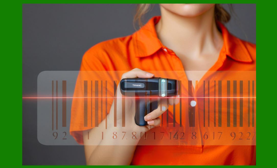
| 6. Medication Administration: When Decoding Results Are Directly Linked to Patients' Bodies | Barcode decoding in healthcare carries the responsibility of patient safety; the consequences of misreads escalate from economic loss to personal injury, making decoding verification far stricter than in retail. | In hospital wards, nurses scan the barcode on a patient's wristband before administering medication, then scan the barcode on the medication packaging. The system compares the two, confirming whether patient identity, medication name, dose, route of administration, and timing are consistent with the physician's orders. If barcode decoding produces a misread -- the patient wristband is read as another patient's ID, or the medication barcode is read as a different drug -- the system may block a correct administration or, worse, allow an incorrect one. | The decoding environment for medical barcodes is fundamentally different from retail. Patient wristbands are typically made of soft materials that experience bending, wrinkling, and exposure to sweat or disinfectants during wear. Barcodes on wristbands are often small to fit wrist width, meaning each module's physical width is narrower, placing higher demands on scanner resolution. Barcodes on medication packaging face similar challenges: the curved surfaces of vials and ampoules can cause perspective distortion during scanning, and some small medication packages leave extremely limited space for barcodes, pushing quiet zone widths to the lower limit of the standard. | Under such conditions, decoder design must tend toward extreme conservatism. Check digit verification in medical scenarios is not an optional optimization but a mandatory gate. Additionally, many medical barcode systems use GS1 standard data structures containing application identifiers that segment data into independent fields such as patient ID, batch number, and expiration date. The decoder must not only correctly read the characters but also verify that these fields' structures conform to GS1 specifications and that field separators appear at expected positions. A 'barely passing' read that might be tolerated in retail should be rejected in medical scenarios. | A deeper difference lies in how decoding results are used. In retail checkout systems, a rejected read merely costs a few extra seconds. In medical administration workflows, if the decoder frequently rejects reads due to poor barcode quality, nurses may be forced to manually enter patient IDs or medication codes -- and manual entry is precisely the error source that barcode systems aim to eliminate. Therefore, medical barcode decoders need to find a very narrow balance between 'rejecting poor-quality reads' and 'avoiding being so picky that manual intervention is forced.' The achievement of this balance often depends on the decoder's deep understanding of specific medical symbologies: it knows which fields in medication barcodes are critical, which character positions are more likely to represent genuine danger when erroneous, and thus assigns different weights during judgment. This semantics-based decoding strategy is something general-purpose retail decoders do not possess. | 
| 7. Automotive Parts Traceability: Batch Precision and the Decoder's 'Intolerant' Requirements | Barcode decoding for automotive manufacturing parts requires extremely high batch traceability precision; a single decoder misread may cause the recall scope for an entire batch of products to be incorrectly expanded or narrowed. | On automotive assembly lines, every critical component -- from engine control units to seatbelt buckles -- carries a barcode label recording its part number, production batch, supplier code, and production date. When these components are installed in vehicles, scanners read the barcodes and bind the component identity to the vehicle identification number, storing it in the manufacturing execution system's database. Years later, if a batch of components is found to be defective, the manufacturer can precisely trace which vehicles used that batch of parts, thereby limiting the recall scope to the necessary size. | The reliability of this traceability chain depends entirely on decoding accuracy. If the decoder misreads a component's batch number as an adjacent batch on the assembly line, the traceability system records incorrect information. When a recall occurs, this error can lead to two consequences: either a batch of actually defective parts is excluded from the recall scope and remains on the road as a safety hazard, or a batch of qualified parts is incorrectly included in the recall, costing the manufacturer millions of dollars in unnecessary expenses. In either case, the root cause can be traced to the judgment the decoder made in that single scan. | The decoding environment for automotive parts barcodes has some unique characteristics. Many component labels are printed directly on metal or plastic surfaces rather than paper labels, meaning barcode contrast may be low and surfaces may locally reflect light due to oil or machining fluid. Assembly line scanners are typically mounted at fixed positions, with components passing through the scan area on conveyors at relatively stable distances and angles, but conveyor vibration may introduce slight motion blur. Additionally, the symbologies widely used in the automotive industry (such as Code 128 or Data Matrix) differ from retail UPC/EAN, with their own encoding rules and verification mechanisms. Code 128 uses three character sets and multiple start pattern variants; the decoder must simultaneously determine the start pattern type and character set switching state during matching, which is far more complex than UPC/EAN's fixed structure. | To address these challenges, decoders in automotive manufacturing are often configured in 'intolerant' mode. Tolerance windows are narrowed, check digit verification is set as a hard failure condition, and any marginal read that might be accepted in retail scenarios is rejected here. The production line does not stop because of a single rejection: components on the conveyor pass through multiple scanning stations, or are scanned multiple times at the same station, and a rejection merely means this particular attempt was not successfully recorded while the next scan will try again. But if a misread is allowed through, the error becomes embedded in the database, and errors in the database are almost impossible to automatically detect in subsequent manufacturing processes. Therefore, the decoding strategy in the automotive industry is the opposite of retail: it trades a slight loss in throughput for the highest possible credibility of every accepted read. | 
| 8. Parcel Sorting and Airline Baggage: Decoding in High-Speed Motion and Fallback Paths | Logistics and aviation scenarios require decoders to complete reads while parcels or baggage are moving at high speed, and decoding failures must have reliable fallback plans because sorting systems cannot stop operating because of one barcode. | At express delivery company sorting centers, parcels move on conveyors at several meters per second, passing sequentially through scan tunnels. Scanners capture barcode images or laser scan lines in the instant parcels pass, and decoders must output tracking numbers in extremely short time. The sorting system directs parcels to the correct chute or shipping container based on this number. A decoding failure means the parcel cannot be automatically sorted and will be sent to an exception handling channel for manual intervention. | Airline baggage handling has a similar rhythm but even less room for error. After passengers check in their baggage at the counter and affix barcode labels, the baggage enters the conveyor system into the sorting area, ultimately being loaded onto the correct flight. If a baggage barcode cannot be read during sorting, the baggage may be misrouted to another conveyor or stranded in the sorting area awaiting manual handling. For flights with tight connection times, a delayed bag may cause passengers to wait extensively at their destination, or even result in complete baggage loss. The unique challenge of airline baggage barcodes lies in how labels are attached: ground staff wrap labels around baggage handles, and the barcode may face any direction, with baggage orientation on the conveyor uncontrollable. Therefore, airline baggage scanning systems typically deploy multiple scanners covering the conveyor from different angles, and the decoder must fuse read results from multiple perspectives. | In these high-speed scenarios, a key principle of decoder design is 'fail fast and retry.' If a candidate interval sequence fails preliminary checks such as guard pattern matching or check digit verification, the decoder should not spend precious time trying to 'repair' it or deeply analyze the cause of failure. A more effective strategy is to immediately abandon the current scan line and wait for the next scan line or next frame. Parcels pass through multiple scanners' fields of view in scan tunnels, and airline baggage passes through multiple read points on conveyors, so retry opportunities are abundant. The decoder's computational resources should be allocated to candidates with reasonable hope of success rather than entanglement with hopeless data. | Additionally, decoding systems in logistics scenarios typically work in conjunction with optical character recognition. Many parcel and baggage labels have human-readable digits printed alongside barcodes. When barcode decoding fails, the system can fall back to visual recognition of characters, matching the recognition result against database records to recover the tracking number. This multimodal redundancy design means the barcode decoder does not need to pursue a 100 percent read rate; it only needs to succeed in the vast majority of cases and leave reliable fallback paths for the remaining. This system-level design thinking, more than optimizing the decoding algorithm itself, better ensures the smooth operation of the logistics chain. | 
| 9. When Decoding Fails: Rejection as a Design Feature, Not a Defect | The decoder's ability to 'refuse to output' is as important as its ability to output correctly, because an undetected erroneous read costs far more than a rejection in most applications. | When discussing the various stages of barcode decoding, one easily overlooked fact is that one of the decoder's most important functions is to remain silent when uncertain. A well-designed decoder is not a machine that tries to squeeze digits out of any input but a cautious arbiter that makes judgments only when evidence is sufficient. Rejection -- outputting a 'cannot decode' signal -- is an active, deliberate design choice, not a manifestation of system failure. | The value of rejection manifests differently across applications. At a retail checkout counter, rejection means the cashier needs to scan again or manually enter, costing seconds. On an automotive assembly line, rejection means a component needs to be retried at the next scanning station, costing production line cycle time. In medical administration, rejection means the nurse needs to rescan or confirm, costing nursing staff time and attention. And in all these scenarios, the cost of misreads far exceeds that of rejection: retail price disputes, automotive recall scope deviations, medical medication errors -- the severity of these consequences is not in the same order of magnitude as a rescan. | The mechanisms by which the decoder achieves 'judicious rejection' are multi-layered. At the most basic level, guard pattern matching and quiet zone verification exclude candidates that do not possess symbol structure at all. At the character decoding level, ratios between interval widths must fall within the tolerance ranges allowed by the encoding table, and any out-of-range candidate is flagged as suspect. At the check digit level, arithmetic consistency provides secondary verification independent of the character decoding process. At the system level, consistency checks across multiple scans -- requiring the same symbol to be interpreted identically on different scan lines or exposures -- further filter pseudo-results that accidentally pass single checks. Each layer increases the number of coincidences required to make an erroneous judgment, thereby exponentially suppressing misread probability. | However, the threshold setting for rejection is always a trade-off. If the decoder is adjusted to be too cautious, it will reject many barcodes that are actually of acceptable quality, leading to reduced operational efficiency and user dissatisfaction. If too lenient, it will begin passing reads in the gray zone, a small fraction of which will be genuine errors. There is no universally optimal solution for this threshold; it must be adjusted according to the risk profile of the application scenario. Healthcare and automotive manufacturing tend toward tighter thresholds, while retail and logistics can moderately relax on the premise of ensuring hard passage of check digit verification. This adjustability itself is a manifestation of the 'digital boundary' concept in decoding circuit design: at the interface between analog signals and digital judgments, deciding whether an ambiguous input should be classified as 'acceptable' or 'unacceptable' is the most consequential decision the decoder executes. | 
| 10. The Irreversible Contraction from Intervals to Bits: The Significance of Information Loss in Decoding | The decoding process is essentially an information contraction process, contracting from interval sequences containing noise and uncertainty to uniquely determined digit strings; the irreversibility of this contraction determines that every choice in design is critical. | Reviewing the entire path from scan line to character output, a profound feature emerges: information is continuously decreasing. The raw photoelectric signal contains rich information about barcode contrast, print quality, scan speed variation, and surface reflection patterns. Digitization compresses it into a list of interval widths. Symbology matching classifies these widths into finite encoding categories. Check digit verification compresses the character sequence into a binary judgment of pass or fail. Ultimately, the decoder outputs a much shorter digit string, and all the subtle information about signal quality is discarded in this process. | This information loss is irreversible. Once the decoder outputs the digit string, downstream systems cannot know whether this output was based on a perfectly clear scan line or on a marginal read that barely passed all tolerance checks. In most cases, this is irrelevant because the tolerance check design already ensures that passing reads have acceptable credibility. But in certain cases, knowing 'how marginal this read was' is valuable. For example, on a gradually degrading barcode label, if the decoder could report 'the margin of this read is shrinking,' the maintenance system could schedule replacement before the label completely fails. Some advanced decoders do attach a signal quality indicator alongside the digit output, but this information is often discarded in standard barcode interfaces, and downstream systems see only a clean digit string. | Understanding the nature of this information contraction helps explain why decoding circuit design cannot focus solely on 'working correctly under ideal conditions.' Decoding under ideal conditions is a solved problem. The real engineering challenge lies in those non-ideal, marginal, noise-and-distortion-filled inputs: when a barcode is covered by crumpled plastic film, when the laser scan line happens to fall on the boundary between two modules, when label print contrast declines due to thermal head aging. At these moments, the judgments the decoder makes -- accept or reject, and if accept, how much implicit trust to assign to this result -- propagate downstream along the data chain, ultimately manifesting in some concrete way at a checkout counter, hospital ward, or assembly station. | 
| 11. Decoder Architecture Under Multi-Symbology Coexistence | A modern decoder often needs to support multiple symbologies simultaneously, and its architecture must make trade-offs between shared hardware and optimizations for specific symbologies. | In real-world deployments, few decoders face only one symbology. Retail checkout scanners may need to read UPC-A, EAN-13, UPC-E (the compressed version for small packages), and occasionally GS1 DataBar (for bulk goods or coupons). Automotive factory scanners may simultaneously face Code 128, Code 39, and Data Matrix. Decoders in medical scenarios may need to handle GS1-128 (a Code 128 variant with application identifiers) and GS1 DataMatrix. This multi-symbology coexistence requirement shapes the architecture of decoding circuits. | A common design is pipeline processing: the front-end signal processing and interval extraction module is common to all symbologies, because regardless of which encoding rule is ultimately matched, the decoder first needs a string of interval widths. This shared front end includes analog filtering, digitization, and logic for extracting width counts from transition sequences. The benefit of a shared front end is low hardware cost and low power consumption, suitable for handheld or embedded devices. The cost is that the front end cannot be deeply optimized for the special needs of a particular symbology -- for example, UPC/EAN quiet zone verification requires retrospective scanning of scan data, while decoding certain two-dimensional symbols requires an entirely different image processing path. | After the interval sequence enters the symbology matching stage, the decoder typically adopts a parallel or fast-switching strategy. If UPC/EAN dominates the application scenario, the decoder can prioritize UPC/EAN matching rules and switch to other symbologies only after consecutive failures. This priority strategy is very effective in retail checkout because the vast majority of products indeed use UPC or EAN. But in a mixed scenario -- such as a site handling both retail goods and logistics parcels -- fixed priority may cause decoding delays for non-dominant symbologies. More flexible designs dynamically adjust attempt order based on historical success rates or exclude obviously mismatched symbologies early based on features such as scan line length and interval count. | Another dimension of multi-symbology coexistence is the difference in verification mechanisms. UPC/EAN's modulo-ten check digit and Code 128's modulo-103 checksum are different arithmetic operations. The decoder needs to know which symbology the current candidate belongs to at the matching stage in order to invoke the correct verification routine. This means symbology identification cannot be entirely deferred until after character decoding; it must gradually become clear during the matching process. Guard pattern recognition plays a role here again: start patterns differ across symbologies, and the decoder preliminarily determines the candidate symbology by recognizing the start pattern, then completes remaining verification within that symbology's rule set. If the preliminary determination is wrong -- for example, a Code 128 symbol's start pattern happens to resemble a UPC/EAN guard pattern -- subsequent character decoding or check digit verification will fail, and the decoder then falls back to other symbology hypotheses. This 'guess first, verify later, fall back on failure' strategy is a practical solution for multi-symbology decoders to achieve high coverage under limited computational resources. | 
| 12. The Philosophy of Decoding Circuits and the Digital Boundary: Between Analog Ambiguity and Digital Certainty | The decoder stands at the interface between the analog world and the digital world; its task is to make deterministic judgments amid ambiguous physical reality, and the inherent tension of this task shapes every design decision. | The core theme of Part V of this book is 'Decoding Circuits and the Digital Boundary.' In the preceding chapters, we have traced the conversion process from photons to electrical signals, from analog waveforms to digital bits. The decoding step described in Chapter 54 is precisely the final link in this conversion chain: the decoder transforms digitized interval sequences into characters with definite meaning, then sends these characters across the boundary to downstream digital systems. On one side of the boundary lies the continuous, noise-filled, uncertain analog physical world. On the other side lies the discrete, zero-and-one-operated digital computing world that demands unambiguous input. The decoder is the gatekeeper between these two worlds. | The gatekeeper's job is never easy. The analog world does not provide 'clean' input. A barcode label should produce a perfect interval sequence under ideal conditions, but ideal conditions rarely exist in reality. Ink droplet spread during printing, paper fiber texture, curved surface reflections from plastic packaging, slight hand tremors during scanning, mechanical vibration of conveyors, changes in ambient light -- all these factors leave their marks on the interval sequence. The decoder must recognize the patterns specified by the symbology from these contaminated traces while also judging how reliable its recognition is. | The digital world, in turn, has uncompromising requirements for input. Downstream databases, inventory systems, billing systems, or medical record systems do not process 'probably' or 'possibly.' They need definite characters, definite digits, definite identifiers. The decoder cannot pass information like 'this interval sequence looks somewhat like a UPC symbol, but I'm not quite sure about the third character' to downstream. It must make a decision: either output a definite character sequence or output a rejection. This leap from ambiguity to certainty is the essential meaning of the digital boundary. | The consequences of this leap are profound. In retail checkout, it determines the price the customer pays. In medical administration, it determines the medication the patient receives. In automotive assembly, it determines the scope of a recall. In logistics sorting, it determines the destination of a parcel. When making these decisions, the decoder does not know how downstream systems will use its output. It is just a circuit executing pattern matching and arithmetic verification. But its designers know, or should know, the weight of these outputs. If a decoder verified in the laboratory with high-quality test labels does not account in its design for the degradation of labels in the real world, the variability of scanning conditions, and the differentiated tolerance for misreads across industries, then its performance after deployment will fail to meet needs it was never explicitly told about. | Therefore, decoding circuit design has never been a purely technical problem. It always involves understanding application scenarios, evaluating failure consequences, and responding to the fundamental challenge of 'making defensible judgments under uncertainty.' The journey from photons to bits does not end at a mathematically elegant algorithm but at an engineering decision that bears concrete responsibility in a concrete context. The interval sequence matching, guard pattern verification, check digit computation, and quiet zone checking described in Chapter 54 are all concrete forms of this decision. They appear to be technical details, but each carries a definition of 'what counts as good enough,' and that definition ultimately comes from the industry the barcode serves, the process, and the people behind that process. | 
| Detailed Chapter Summary: This chapter began with the interval sequence matching described in Chapter 54 and systematically unfolded the transformation chain from raw width data to meaningful characters in the barcode decoding process. UPC/EAN guard patterns provide the decoder with a fixed rhythm anchoring symbol boundaries, making progressive, revocable reasoning possible. Check digit computation provides secondary verification independent of character decoding through a simple modulo-ten arithmetic problem, but its interception capability is not absolute and therefore requires coordination with other mechanisms. Quiet zone verification excludes large numbers of pseudo-candidates at the front of the decoding pipeline, and the setting of its strictness requires balancing label quality reality against false trigger risk. On this foundation, we examined five fundamentally different application domains: retail checkout pursues the ultimate balance of speed and accuracy, preferring rejection over misread; medical administration directly links decoding results to patient safety, demanding the strictest verification strategy; automotive parts traceability centers on batch precision, where the decoder's intolerance is a prerequisite for traceability reliability; logistics sorting and airline baggage rely on multiple scan opportunities and multimodal fallback during high-speed motion, with systematic fallback paths for decoding failures. Running through all these scenarios is the value of rejection as a design feature and the engineering consequences of irreversible information contraction during decoding. Multi-symbology coexistence shapes the architecture of shared front ends and differentiated matching strategies. Ultimately, the decoder stands at the boundary between analog ambiguity and digital certainty, and each of its judgments -- accept, reject, or fall back -- is an engineering decision made under uncertainty that carries concrete industry consequences. |
|
 cs@easiersoft.com