Article 45: The Motor Drive A Bidirectional H-Bridge and the Art of Sinusoidal Current | Summary | This article explains how the scan motor in a laser barcode scanner is driven by a bidirectional H-bridge that synthesizes a sinusoidal current through pulse-width modulation at a frequency far above the mechanical resonance of the moving-coil actuator. It walks through why a sinusoidal drive is used instead of a simple square wave, how the H-bridge creates bidirectional current, why the PWM frequency must sit well above mechanical resonance, and what all of this means in real products across retail, logistics, healthcare, manufacturing, and other industries. | 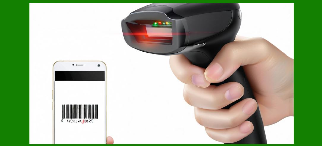
| 1. Introduction: Why the Motor Drive Deserves Its Own Chapter | The motor drive is the invisible hand that turns electrical commands into the graceful sweep of a laser spot. In the previous articles of this part, we examined the flying spot itself, the optics that shape it, the photodetector that catches its reflection, and the mechanical assembly that holds everything together. Now we arrive at the electronics that actually move the mirror: the motor drive circuit. This circuit is small, often occupying a few square centimeters of a circuit board, yet it determines whether the scan line is smooth, stable, and quiet, or jittery, noisy, and unreliable. | A barcode scanner's scan motor is usually a moving-coil actuator, a close cousin of the voice coil motor found in hard disk drives and smartphone camera autofocus systems. It consists of a coil of wire suspended in a permanent magnetic field. When current flows through the coil, a force pushes the coil, and the attached mirror, in one direction. When the current reverses, the force reverses. The mirror therefore oscillates back and forth, sweeping the laser beam across the barcode. The elegance of this arrangement is its simplicity: one coil, one magnet, one mirror, and a drive circuit that alternates the current. | But the simplicity of the concept hides the sophistication of the implementation. A moving-coil actuator is a mechanical resonator with a natural frequency, a mass, a stiffness, and a damping factor. If you drive it with a crude square wave, it will ring, overshoot, and vibrate at frequencies you did not intend. If you drive it with a current that is not smooth, the mirror will tremble, and the laser spot will wobble. The result is a scan line that is uneven in speed, which smears the barcode signal in time and makes decoding harder. The motor drive circuit exists to prevent exactly this outcome. | The standard solution, refined over decades of scanner design, is a bidirectional H-bridge that synthesizes a sinusoidal current waveform using pulse-width modulation at a frequency well above the mechanical resonance of the actuator. Each element of that sentence matters. The H-bridge allows current to flow in either direction, so the mirror can be pushed both ways. The sinusoidal waveform matches the natural motion of a resonant mechanical system, so the mirror moves smoothly rather than jerking. The PWM frequency is chosen high enough that the mirror's inertia filters out the switching ripple, so the coil current looks like a pure sine wave to the mechanics. Together, these three ideas form the backbone of nearly every laser scan engine in the world. | This article unpacks each idea in turn, then shows how they play out in real products across many industries. We will look at retail point-of-sale scanners that must survive millions of scans, warehouse scanners that must read barcodes at a distance, medical scanners that must be quiet and reliable, and industrial scanners that must endure dust, heat, and vibration. In each case, the motor drive circuit is a quiet hero, and understanding it explains why some scanners feel solid and others feel flimsy. | 
| 2. The Moving-Coil Actuator: A Mechanical Resonator in Disguise | A moving-coil actuator is a mechanical resonator in disguise, and understanding its resonance explains why the drive current must be sinusoidal. Every mechanical system with mass and stiffness has a natural frequency at which it prefers to oscillate. A pendulum swings at a frequency set by its length. A guitar string vibrates at a frequency set by its tension and mass. A scan mirror attached to a coil and a torsion spring behaves the same way. If you displace it and let go, it will oscillate at its natural frequency, gradually damping out. | This natural frequency is typically in the range of tens to a few hundred Hertz for a barcode scanner mirror. The exact value depends on the mirror's moment of inertia, the stiffness of the suspension, and the mass of the coil. Designers choose this frequency deliberately. It sets the scan rate, which in turn sets how many times per second the laser spot sweeps across the barcode. A supermarket scanner might sweep a few hundred times per second, while a long-range industrial scanner might sweep more slowly to gather more light per sweep. | The key insight is that a resonant mechanical system responds very differently to different drive waveforms. If you drive it at its natural frequency with a sinusoidal force, it builds up a large amplitude oscillation with relatively little energy, because each push arrives at exactly the right moment to add to the motion. This is resonance, and it is the same effect that lets a child on a swing go higher and higher with small pushes timed to the swing's rhythm. If you drive it with a square wave, you inject energy at many frequencies at once, including frequencies far from resonance. The system responds to the resonant component strongly and to the other components weakly, but those other components still excite unwanted vibrations and ringing. | A square-wave drive also creates sharp transitions, and sharp transitions mean high acceleration. High acceleration means high force on the coil and suspension, which means stress, wear, and acoustic noise. A scanner driven by a square wave tends to buzz, whine, and wear out faster than one driven by a sine wave. The sine wave, by contrast, has only one frequency component, so it excites only the intended motion and nothing else. The mirror glides back and forth in a smooth, predictable rhythm, and the laser spot traces an even line. | There is another reason for sinusoidal drive: linearity. The relationship between current and force in a moving-coil actuator is approximately linear over a range, but nonlinearities appear at large excursions and high speeds. A sine wave keeps the actuator within its linear range more of the time, so the mirror's motion tracks the drive current faithfully. This faithfulness matters because the scanner's decoding software assumes the spot moves at a known, predictable speed. If the speed varies within a sweep, the barcode signal stretches and compresses in time, and the decoder must work harder to recover the pattern. | Finally, sinusoidal drive is gentler on the suspension. The torsion springs or flexures that hold the mirror are designed for a certain stress level. A sine wave distributes that stress smoothly over the cycle, while a square wave concentrates it at the transitions. Over millions of cycles, this difference determines whether the scanner lasts five years or fifteen. Reliability engineers love sine waves for this reason alone. | 
| 3. The H-Bridge: Making Current Flow Both Ways | The H-bridge is the circuit that makes current flow both ways through the coil, and its name comes from the shape of its schematic. Imagine four switches arranged in a square, with the coil connected across the middle. The left side of the square is connected to the positive supply, the right side to ground, and the coil bridges the top and bottom of the middle. By closing different pairs of switches, you can push current through the coil from left to right or from right to left. The four switches form an H shape around the coil, hence the name. | In modern scanner electronics, the switches are not mechanical relays but transistors, usually metal-oxide-semiconductor field-effect transistors, or MOSFETs. These transistors act as fast, efficient valves for current. When a transistor is on, it conducts with very low resistance, wasting little power as heat. When it is off, it blocks current almost completely. By turning transistors on and off in carefully timed patterns, the H-bridge can steer current through the coil in either direction, with any magnitude from zero to maximum. | The H-bridge has three possible states that matter for scanner design. In the forward state, one diagonal pair of transistors is on, and current flows through the coil in one direction. In the reverse state, the other diagonal pair is on, and current flows the other way. In the brake or coast state, either the top pair or the bottom pair is on, shorting the coil and allowing the current to decay quickly, or all transistors are off, allowing the current to circulate through protective diodes. The brake state is important because a moving-coil actuator stores energy in its magnetic field, and that energy must go somewhere when the drive changes direction. A well-designed H-bridge handles this energy gracefully, protecting the transistors and keeping the current smooth. | The H-bridge must also handle the back electromotive force generated by the moving coil. When the coil moves through the magnetic field, it acts like a generator and produces a voltage that opposes the drive voltage. This back electromotive force is proportional to the coil's velocity, and it is the mechanical equivalent of a back-pressure in a hydraulic system. The H-bridge must supply enough voltage to overcome this back electromotive force and still push the desired current through the coil. This is why the supply voltage for a scan motor is often higher than the steady-state voltage needed to hold a given current. The extra voltage provides the headroom to accelerate the mirror quickly and to overcome the back electromotive force at high speed. | Another subtlety is shoot-through, a condition where both transistors in one leg of the H-bridge turn on at the same time, creating a direct short from supply to ground. Shoot-through can destroy transistors in microseconds, so the drive circuit includes dead time, a brief interval when both transistors in a leg are off during a switching transition. The dead time is short, typically tens to hundreds of nanoseconds, but it is essential. Designing the dead time correctly is one of the small arts of motor drive design, because too little risks shoot-through and too much distorts the current waveform. | The H-bridge also needs protection against inductive spikes. When a transistor turns off, the coil's inductance tries to keep current flowing, and the resulting voltage spike can exceed the transistor's rating. Protection diodes, either built into the MOSFETs or added externally, provide a path for this current to circulate safely. Some designs use a capacitor across the supply to absorb the energy, and some use active clamping to recycle it. These details rarely appear in a product brochure, but they determine whether a scanner survives a power surge or a stalled mirror. | 
| 4. Pulse-Width Modulation: Sculpting a Sine Wave from Switches | Pulse-width modulation is the technique that turns the H-bridge's on-off switching into a smooth sinusoidal current, and it works by varying the fraction of time the switches are on. The idea is simple: if you switch the supply voltage on and off rapidly, and you vary the on-time as a fraction of the total period, the average voltage seen by the coil tracks that fraction. If the fraction itself varies sinusoidally over time, the average voltage follows a sine wave. The coil's inductance and the mechanical inertia of the mirror then filter out the rapid switching, leaving a smooth current and a smooth motion. | The fraction of time the switch is on is called the duty cycle. A duty cycle of fifty percent gives an average voltage of half the supply. A duty cycle of seventy-five percent gives three-quarters of the supply. By modulating the duty cycle sinusoidally, the drive circuit synthesizes a sinusoidal average voltage, and because the coil current follows the average voltage (subject to the coil's inductance), the current is also sinusoidal. This is the heart of the technique: the switches only ever produce full-on or full-off, but the average, filtered by the mechanics, is a pure sine. | The frequency of the switching, called the PWM frequency, is chosen to be well above both the mechanical resonance and the audible range. Mechanical resonance is typically tens to a few hundred Hertz, and audible range extends to about twenty thousand Hertz. A PWM frequency of twenty to one hundred kilohertz sits comfortably above both. At these frequencies, the mirror's inertia cannot respond to individual switching pulses, so the mirror sees only the average. The coil's inductance also opposes rapid current changes, further smoothing the ripple. The result is a current waveform that is sinusoidal to within a few percent, with a small high-frequency ripple superimposed. | Why does the PWM frequency need to be well above mechanical resonanceBecause any excitation near resonance is amplified by the mechanical system, and any excitation far above resonance is attenuated. If the PWM frequency were close to resonance, the switching ripple would be amplified into visible mirror vibration, producing a wobbly scan line and audible buzz. By placing the PWM frequency far above resonance, the mechanical system acts as a low-pass filter, attenuating the ripple by a large factor. The higher the PWM frequency relative to resonance, the more attenuation, and the smoother the motion. | There is a trade-off, however. Higher PWM frequencies mean more switching losses in the transistors, because each switching transition dissipates a small amount of energy as heat. Higher frequencies also demand faster gate drivers and tighter layout to avoid electromagnetic interference. Designers balance these factors, often choosing a PWM frequency in the tens of kilohertz, high enough for good filtering but low enough for acceptable efficiency. Some designs use a PWM frequency that is deliberately synchronized to the scan rate or to a multiple of it, so that any residual ripple is periodic and predictable, which helps the signal processing. | The PWM frequency also affects audible noise. Although the fundamental PWM frequency is above the audible range, the switching transitions can excite mechanical resonances at lower frequencies through nonlinear effects, or the coil itself can sing at the PWM frequency and its harmonics. Designers sometimes spread the PWM frequency slightly over time, a technique called spread-spectrum modulation, to smear the switching energy across a band and reduce peak acoustic noise. This is especially important in quiet environments such as hospitals and libraries, where a whining scanner would be unacceptable. | 
| 5. Closing the Loop: Sensing Current and Position | The motor drive does not operate blindly; it closes a loop around the current, and sometimes around the position, to keep the mirror motion faithful to the command. The most basic loop senses the coil current and adjusts the PWM duty cycle to make the actual current match the desired sinusoidal reference. This current loop is fast, operating at the PWM frequency or a fraction of it, and it rejects disturbances such as supply voltage fluctuations, temperature changes in the coil resistance, and back electromotive force variations. Without a current loop, the current would drift with temperature and supply, and the scan amplitude would vary. | A more sophisticated scanner also closes a position loop, sensing the mirror angle and adjusting the current command to track a desired angular trajectory. Position sensing can be done with a small optical sensor that detects a flag attached to the mirror, with a magnetic sensor that detects the coil's field, or with a capacitive sensor that measures the gap between the mirror and a fixed electrode. The position loop is slower than the current loop but ensures that the mirror actually reaches the commanded angle, compensating for variations in spring stiffness, damping, and friction. | The combination of current and position loops gives the scanner a remarkable property: it can maintain a stable scan amplitude and frequency despite manufacturing tolerances, temperature changes, and aging. This stability is what allows a scanner to decode barcodes reliably over years of use. Without feedback, a scanner might work perfectly on the day it is manufactured and degrade as the spring softens or the magnet weakens. With feedback, the drive circuit continuously adapts, keeping the flying spot on its intended path. | Some scanners go further and use the back electromotive force itself as a position signal. Because the back electromotive force is proportional to velocity, integrating it gives position, and the drive circuit can estimate the mirror angle without a separate sensor. This technique, called sensorless control, saves cost and space, and it is common in high-volume consumer scanners. It requires accurate modeling of the coil resistance and inductance, and it works best when the current waveform is smooth and predictable, which is another reason sinusoidal drive is preferred. | The feedback loop also enables soft start and soft stop. When the scanner powers on, the drive circuit ramps the scan amplitude up gradually rather than jumping to full amplitude, avoiding mechanical shock and audible pop. When the scanner goes to sleep, it ramps down gently. These behaviors are invisible to the user but extend the life of the suspension and reduce acoustic noise. They are made possible by the combination of the H-bridge, the PWM, and the feedback loop working together. | 
| 6. Why Not a Simple Square WaveThe Case for Sinusoidal Drive | A simple square wave is cheaper and simpler to generate than a sine wave, so why do scanner designers bother with sinusoidal driveThe answer lies in the physics of resonance, the economics of reliability, and the demands of decoding. A square wave contains energy at the fundamental frequency and at every odd harmonic. The fundamental drives the intended motion, but the harmonics excite higher mechanical modes, producing ringing, buzzing, and wear. The mirror may wobble at frequencies that the optics cannot tolerate, and the scan line may develop ripples that confuse the decoder. | The harmonics also create acoustic noise. A square-wave-driven scanner often emits a sharp buzz or whine at the fundamental and its harmonics, which is unpleasant in quiet environments and can even be a safety concern in medical settings where patients expect calm. A sine-wave-driven scanner is much quieter, often producing only a faint hum at the scan frequency. This quietness is a selling point in retail, healthcare, and office environments. | Reliability is another factor. The sharp transitions of a square wave create high peak currents and high peak forces, which stress the coil, the suspension, and the solder joints. Over millions of cycles, these stresses accumulate and lead to fatigue failures. A sine wave distributes the stress evenly, reducing peak forces and extending life. Field data from scanner manufacturers consistently show that sinusoidal drive improves mean time between failures, especially in high-usage environments such as supermarket checkout lanes. | Decoding performance is a third factor. The decoder expects the spot to move at a predictable speed, and any deviation stretches or compresses the barcode signal in time. A square wave produces speed variations within each sweep, because the mirror accelerates sharply at the transitions and moves more slowly elsewhere. A sine wave produces a smoother speed profile, and the decoder can compensate for the known sinusoidal speed variation more easily. In practice, the difference shows up as a higher first-read rate, especially on poor-quality or damaged barcodes. | Finally, sinusoidal drive reduces electromagnetic interference. A square wave has fast edges that radiate broadband energy, which can couple into the photodetector circuit and corrupt the signal. A sine wave has slower edges and narrower spectral content, so it interferes less with the sensitive analog front end. This matters because the photodetector signal is often in the microvolt range, and any interference can swamp it. By keeping the motor drive spectrally clean, the designer makes the receiver's job easier. | 
| 7. Real-World Application: Retail Point-of-Sale Scanners | Retail point-of-sale scanners are the most familiar application of the motor drive, and they illustrate every principle in this article. A supermarket checkout scanner must scan barcodes thousands of times per day, often on the first attempt, and it must do so reliably for a decade or more. The motor drive inside such a scanner is typically a bidirectional H-bridge driving a moving-coil actuator with a sinusoidal current at a scan rate of a few hundred Hertz, with PWM at tens of kilohertz. | The sinusoidal drive keeps the scan line smooth, which is essential for reading barcodes on curved or wrinkled packaging. A wobbly line would produce a smeared signal, and the decoder would fail on all but the cleanest barcodes. The H-bridge allows the mirror to be driven symmetrically, so the scan line extends equally on both sides of center, maximizing the usable scan width. The PWM frequency is chosen high enough to be inaudible, because checkout lanes are noisy but customers still notice a whining scanner, and because the scanner sits close to the cashier's ears all day. | Retail scanners also benefit from the feedback loop. The scan amplitude must remain constant as the scanner ages, because the optics are aligned for a specific scan width. If the amplitude drifts, the scan line may no longer cover the full window, and barcodes near the edges may be missed. The current loop and position loop keep the amplitude stable, compensating for spring fatigue and magnet aging. This stability is why a ten-year-old supermarket scanner can still read barcodes as well as it did on day one. | The motor drive also enables power management. Retail scanners often have a sleep mode that stops the motor when no barcode has been scanned for a while, saving energy and extending motor life. When a barcode approaches, the scanner wakes up and ramps the motor back to full amplitude in a fraction of a second. The soft-start ramp avoids mechanical shock and audible pop, and the fast wake-up ensures the first scan attempt succeeds. These behaviors are orchestrated by the motor drive circuit in concert with the scanner's microcontroller. | 
| 8. Real-World Application: Warehouse and Logistics Scanners | Warehouse and logistics scanners face different demands: long range, high speed, and ruggedness. A warehouse scanner may need to read a barcode on a pallet several meters away, which requires a narrow, well-collimated laser beam and a slow, precise scan. The motor drive must produce a stable, low-jitter scan line so the beam stays on the barcode long enough to gather sufficient light. Sinusoidal drive with a well-regulated current loop is essential here, because any jitter would smear the return signal and reduce range. | Logistics scanners also operate in harsh environments with dust, vibration, and temperature extremes. The motor drive must tolerate supply voltage fluctuations from forklift power systems, temperature swings that change coil resistance, and mechanical shocks from being dropped or bumped. The current loop rejects supply and temperature disturbances, and the H-bridge's protection features guard against inductive spikes and shoot-through. The sinusoidal drive reduces peak forces, so the suspension survives shocks better than it would with square-wave drive. | High-speed sorting lines demand fast scan rates and rapid wake-up. A parcel moving at two meters per second must be scanned in the fraction of a second it spends in the scan window. The motor drive must ramp up quickly, maintain a stable amplitude, and ramp down without overshoot. The combination of a high PWM frequency, a fast current loop, and a well-damped mechanical system makes this possible. The sinusoidal drive ensures that the mirror does not ring after the ramp, which would blur the scan line during the critical reading interval. | Warehouse scanners also often use oscillating mirrors with larger excursions than retail scanners, which means higher forces and more demanding motor drive. The H-bridge must supply higher current and handle higher back electromotive force, and the PWM frequency must be high enough to filter the larger inductance. Designers often use a higher supply voltage for these scanners to provide the necessary headroom. The principles remain the same, but the component ratings and thermal design become more critical. | 
| 9. Real-World Application: Healthcare and Laboratory Scanners | Healthcare and laboratory scanners demand quiet operation, high reliability, and freedom from electromagnetic interference. A scanner in a hospital ward or a clinical laboratory must not disturb patients or sensitive instruments, and it must work flawlessly because a failed scan can delay diagnosis or treatment. The motor drive's sinusoidal current and high PWM frequency make the scanner nearly silent, and the H-bridge's clean switching reduces electromagnetic emissions that could interfere with medical equipment. | Laboratory scanners often read small barcodes on test tubes and microplates, which requires a fine, stable scan line. The motor drive's current loop keeps the scan amplitude constant despite temperature changes in the laboratory, and the position loop ensures the line stays centered on the sample. The sinusoidal drive minimizes jitter, so the small barcode features are resolved cleanly. In some laboratory scanners, the motor drive also supports variable scan amplitudes, allowing the scanner to zoom in on small barcodes or zoom out for larger ones. | Healthcare scanners also need to be robust against cleaning agents and disinfection protocols. The motor drive electronics are usually sealed or conformally coated, and the H-bridge is designed to tolerate the temperature and humidity variations of a clinical environment. The sinusoidal drive's lower peak currents reduce heating, which helps keep the electronics within their safe operating range. The feedback loop maintains performance as components age, which is important in equipment that may be used for a decade or more. | 
| 10. Real-World Application: Manufacturing and Industrial Automation | Manufacturing and industrial automation scanners operate in the harshest conditions and demand the highest reliability. A scanner on a production line may be exposed to metal dust, coolant mist, welding sparks, and vibrations from heavy machinery. The motor drive must be rugged, protected, and thermally robust. The H-bridge's protection features, including overcurrent shutdown, thermal shutdown, and inductive spike clamping, are essential here, and the sinusoidal drive's lower peak forces reduce wear on the suspension. | Industrial scanners often scan at high rates to keep up with fast-moving products, and they must maintain a stable scan line despite vibration. The current loop rejects vibration-induced disturbances in the back electromotive force, and the position loop, if present, corrects for any mirror deflection caused by external vibration. The PWM frequency is chosen high enough to avoid exciting mechanical resonances in the scanner housing, which could amplify vibration and blur the scan line. | Some industrial scanners use a rotating polygon mirror instead of an oscillating mirror, and these have different motor drive requirements. A polygon mirror spins continuously in one direction, so the motor drive is a three-phase brushless direct current drive rather than an H-bridge. However, the principles of smooth current, high PWM frequency, and closed-loop control still apply. The sinusoidal commutation of a brushless motor is the rotational analogue of the sinusoidal drive of a moving-coil actuator, and the same benefits of low noise, low vibration, and long life apply. | Industrial scanners also benefit from diagnostic features enabled by the motor drive. The current loop's error signal can indicate a failing suspension or a foreign object obstructing the mirror. The position loop's correction signal can indicate bearing wear or spring fatigue. These diagnostics allow predictive maintenance, reducing downtime on production lines. The motor drive thus becomes not just an actuator but a sensor of mechanical health. | 
| 11. Real-World Application: Automotive and Transportation | Automotive and transportation applications use barcode scanners in parts tracking, baggage handling, toll collection, and vehicle identification. These scanners must operate over wide temperature ranges, from freezing warehouses to hot engine compartments, and they must tolerate vibration and shock. The motor drive's current loop compensates for temperature-induced changes in coil resistance, and the H-bridge's protection features guard against load dumps and voltage spikes from vehicle power systems. | Baggage handling scanners at airports must read barcodes on luggage tags at high speed and from varying angles. The motor drive must produce a stable scan line despite the vibration of the conveyor system, and it must wake up quickly when a bag enters the scan tunnel. The sinusoidal drive's smooth motion reduces jitter, and the high PWM frequency keeps the drive inaudible in the noisy baggage hall. The feedback loop maintains amplitude despite temperature changes in the unheated or uncooled tunnel. | Toll collection scanners must read vehicle tags at highway speeds, often in direct sunlight and rain. The motor drive must be robust against solar heating and moisture, and it must maintain a stable scan line despite wind-induced vibration. The sinusoidal drive's low peak forces reduce wear on the suspension, which is important for equipment that operates continuously for years. The current loop's rejection of supply fluctuations keeps the scan amplitude stable as the vehicle's electrical system varies. | 
| 12. Real-World Application: Consumer Electronics and Embedded Scanners | Consumer electronics and embedded scanners, such as those in self-service kiosks, mobile computers, and wearable devices, demand small size, low power, and low cost. The motor drive must fit into a tiny circuit board, often integrated into an application-specific integrated circuit, and it must consume little power to preserve battery life. The H-bridge in these devices uses small MOSFETs with low gate charge, and the PWM frequency is chosen to balance filtering against switching losses. | Embedded scanners often use a moving-coil actuator with a small mirror and a high resonance frequency, which allows a higher scan rate in a smaller package. The motor drive's sinusoidal current and high PWM frequency keep the scanner quiet and smooth, which matters in consumer devices that are used close to the face and ears. The current loop maintains amplitude despite battery voltage droop, so the scanner works as well at low battery as at full charge. | Low power is a special challenge. The motor drive must ramp down quickly when idle and ramp up quickly when needed, without wasting energy in the transitions. The H-bridge's brake state allows the coil current to decay quickly, and the soft-start ramp avoids overshoot that would waste energy and stress the suspension. Some embedded scanners use a pulsed drive that activates the motor only when a barcode is present, further saving power. The sinusoidal drive is essential here because pulsed operation with a square wave would produce audible clicks and mechanical shock. | 
| 13. The Role of the Microcontroller and Firmware | The microcontroller and firmware are the brains behind the motor drive, generating the sinusoidal reference, sequencing the H-bridge switches, and closing the feedback loops. In a typical scanner, the microcontroller runs a timer that produces the PWM signals, and a lookup table or a digital oscillator generates the sinusoidal reference. The firmware reads the current sensor and the position sensor, computes the error, and adjusts the PWM duty cycle to minimize it. This is a classic control loop, implemented in software and executed thousands of times per second. | The firmware also handles the startup sequence, ramping the amplitude from zero to full over a controlled interval, and the shutdown sequence, ramping down gently. It monitors for faults, such as overcurrent or overtemperature, and shuts down the drive if a fault is detected. It may also implement spread-spectrum modulation to reduce acoustic noise, or adaptive control to compensate for aging. The firmware is where the motor drive's behavior is defined, and its quality determines whether the scanner feels responsive and reliable. | Firmware also enables calibration. During manufacturing, the scanner measures the actual scan amplitude and frequency and stores calibration constants in nonvolatile memory. At runtime, the firmware uses these constants to set the reference amplitude and frequency, ensuring that every scanner behaves consistently despite manufacturing tolerances. This calibration is why two scanners of the same model feel identical to the user, even though their mechanical components differ slightly. | 
| 14. Thermal Design and Power Dissipation | Thermal design is a critical but often overlooked aspect of the motor drive, because the H-bridge and the coil both dissipate power as heat. The H-bridge's transistors dissipate power during conduction and switching, and the coil dissipates power as current flows through its resistance. If the heat is not removed, the transistors can overheat and fail, and the coil resistance can rise, reducing the current and the scan amplitude. Good thermal design keeps the temperatures within safe limits and maintains performance over the operating range. | Conduction losses in the H-bridge are proportional to the square of the current and the on-resistance of the transistors. Low on-resistance MOSFETs reduce these losses, but they are larger and more expensive. Switching losses are proportional to the PWM frequency and the switching energy of the transistors. Higher PWM frequencies improve filtering but increase switching losses. Designers balance these factors, often choosing a PWM frequency and transistor size that minimize total losses for the expected operating conditions. | The coil's resistance also dissipates power, and this power is often comparable to the H-bridge losses. A moving-coil actuator with a low-resistance coil dissipates less power but requires higher current for the same force, which increases conduction losses in the H-bridge. A high-resistance coil dissipates more power but requires less current. The optimal design depends on the supply voltage, the required force, and the thermal environment. In sealed scanners, the heat must escape through the housing, so thermal paths are designed carefully. | Temperature also affects the current loop. As the coil heats up, its resistance increases, and the current for a given voltage decreases. The current loop compensates by increasing the duty cycle, maintaining the desired current. This compensation works up to the point where the H-bridge runs out of headroom, at which point the scan amplitude begins to droop. Designers ensure that the supply voltage and the H-bridge rating provide enough headroom for the expected temperature range, so the scanner maintains full performance even when hot. | 
| 15. Electromagnetic Compatibility and Noise | Electromagnetic compatibility is a major concern for the motor drive, because the H-bridge's switching creates fast voltage and current transitions that can radiate and conduct interference. The scanner must meet regulatory limits for electromagnetic emissions, and it must not interfere with its own sensitive photodetector circuit. Good layout, shielding, and filtering are essential, and the choice of PWM frequency and switching speed affects the emission spectrum. | The H-bridge's switching edges are the main source of high-frequency emissions. Faster edges radiate more energy at higher frequencies, but slower edges increase switching losses. Designers often use gate resistors to control the edge rate, balancing emissions against efficiency. They also place the H-bridge close to the coil, minimize loop areas in the layout, and use ground planes and shielding to contain the fields. These measures are especially important in compact scanners where the motor drive and the photodetector share the same circuit board. | The sinusoidal drive itself helps with electromagnetic compatibility, because it concentrates the drive energy at the scan frequency and its harmonics rather than spreading it across a broad spectrum. The PWM ripple is at a high frequency and can be filtered with a small inductor or capacitor, reducing conducted emissions. The current loop also helps by rejecting supply noise, so the drive does not amplify disturbances. Together, these design choices make the scanner both quiet and compliant. | 
| 16. Reliability and Lifetime Considerations | Reliability is the ultimate test of the motor drive, because a scanner that fails in the field damages the customer's operations and the manufacturer's reputation. The motor drive's reliability depends on the H-bridge's robustness, the coil's insulation, the suspension's fatigue life, and the firmware's fault handling. Each of these is designed and tested to survive millions of cycles and years of operation. | The H-bridge's robustness comes from conservative ratings, protection features, and careful thermal design. The transistors are rated for voltages and currents well above the expected maximum, so transients and faults do not destroy them. Overcurrent protection shuts down the drive if the current exceeds a safe limit, and thermal protection shuts it down if the temperature rises too high. These features are tested by deliberately creating faults and verifying that the drive survives. | The coil's insulation must withstand the voltage spikes from switching and the thermal cycling from repeated operation. Manufacturers use high-temperature wire and impregnation to ensure long life. The suspension's fatigue life is tested by running the scanner continuously for millions of cycles and measuring the spring constant and damping. The sinusoidal drive extends this life by reducing peak stresses, and the soft-start and soft-stop ramps avoid shock loads. | Firmware fault handling is the last line of defense. If the drive detects an overcurrent or overtemperature condition, it shuts down the motor, flags an error, and waits for the condition to clear. It may also retry a limited number of times before declaring a permanent fault. This behavior prevents a transient fault from becoming a permanent failure and allows the scanner to recover gracefully. The combination of robust hardware and intelligent firmware makes the motor drive one of the most reliable subsystems in a laser scanner. | 
| 17. Design Trade-Offs and Practical Wisdom | Designing a motor drive involves many trade-offs, and practical wisdom accumulated over decades of scanner design guides the choices. The PWM frequency trades filtering against efficiency and emissions. The transistor size trades on-resistance against gate charge and cost. The coil resistance trades power dissipation against current requirement. The feedback loop bandwidth trades disturbance rejection against stability and noise. Each choice affects the scanner's performance, cost, and reliability. | One practical rule is to keep the PWM frequency at least ten times the mechanical resonance, and preferably higher. This ensures strong attenuation of the switching ripple and avoids exciting mechanical modes. Another rule is to keep the current loop bandwidth well below the PWM frequency but well above the scan frequency, so the loop rejects disturbances without interacting with the switching. A third rule is to design the soft-start ramp to be fast enough for user responsiveness but slow enough to avoid overshoot and audible pop. | Layout wisdom is equally important. Keep the H-bridge close to the coil to minimize loop area and parasitic inductance. Use a solid ground plane under the H-bridge to contain fields and provide a return path. Place the current sensor close to the H-bridge and filter its output to reject switching noise. Route the PWM signals away from the photodetector circuit to avoid crosstalk. These details are rarely taught in textbooks but are learned through experience and passed down through design reviews. | 
| 18. The Future of Motor Drive in Laser Scanners | The future of motor drive in laser scanners is shaped by trends toward smaller size, lower power, higher speed, and greater intelligence. Integrated motor drive chips combine the H-bridge, the current sensor, the gate driver, and the control loop in a single package, reducing size and cost. These chips often include digital interfaces that allow the firmware to configure the drive parameters and read diagnostic data, enabling adaptive control and predictive maintenance. | Lower power is driven by battery-operated scanners and energy-conscious designs. New H-bridge topologies and control techniques reduce switching losses and improve efficiency, extending battery life. Sleep modes and pulsed operation reduce average power, and energy harvesting may eventually power some scanners. The sinusoidal drive remains essential because it minimizes peak currents and mechanical losses, which are significant at low power levels. | Higher speed is driven by fast sorting and high-throughput applications. Faster scan rates require higher mechanical resonance and higher PWM frequencies, which in turn require faster transistors and better thermal design. The control loop must also be faster, which demands more powerful microcontrollers and more efficient firmware. These trends push the motor drive toward higher integration and greater digital control. | Greater intelligence is driven by the desire for self-diagnosing and self-calibrating scanners. The motor drive's current and position signals contain rich information about the mechanical system's health, and machine learning algorithms can analyze this information to detect impending failures. Adaptive control can compensate for aging and environmental changes, maintaining performance over the scanner's life. These capabilities turn the motor drive from a simple actuator into a smart subsystem that contributes to the scanner's overall reliability and user experience. | 
| 19. Detailed Summary | The motor drive in a laser barcode scanner is a bidirectional H-bridge that synthesizes a sinusoidal current through pulse-width modulation at a frequency well above the mechanical resonance of the moving-coil actuator. This design combines three essential ideas: bidirectional current flow, sinusoidal waveform, and high-frequency switching. Each idea addresses a specific physical reality, and together they produce the smooth, stable, quiet, and reliable scan motion that barcode scanning depends on. | The moving-coil actuator is a mechanical resonator with a natural frequency set by its mass and stiffness. Driving it with a sinusoidal current at or near resonance produces large, smooth motion with little energy, while driving it with a square wave excites unwanted modes, causes ringing and noise, and stresses the suspension. The sinusoidal drive matches the physics of the resonator, producing clean motion, low acoustic noise, long life, and predictable scan speed that the decoder can rely on. | The H-bridge is the circuit that steers current through the coil in either direction. Its four transistors act as fast switches, and its forward, reverse, and brake states allow the drive to accelerate, decelerate, and reverse the mirror smoothly. Protection against shoot-through, inductive spikes, and overcurrent ensures that the H-bridge survives the demanding electrical environment of a scanner. The H-bridge's ability to handle back electromotive force is essential for maintaining current at high mirror speeds. | Pulse-width modulation sculpts the sinusoidal current by varying the duty cycle of the H-bridge switches. The PWM frequency is chosen well above mechanical resonance and the audible range, so the mirror's inertia and the coil's inductance filter the switching ripple, leaving a smooth current. The trade-off between filtering and switching losses guides the choice of PWM frequency, and techniques such as spread-spectrum modulation reduce acoustic noise. The PWM frequency also affects electromagnetic compatibility, and careful layout and filtering keep emissions within regulatory limits. | Feedback loops close the gap between command and reality. The current loop ensures that the coil current matches the sinusoidal reference despite supply fluctuations and temperature changes. The position loop, where present, ensures that the mirror angle tracks the desired trajectory despite mechanical variations. Sensorless control uses back electromotive force to estimate position, saving cost and space. Soft-start and soft-stop ramps avoid mechanical shock and audible pop, extending life and improving user experience. | Real-world applications illustrate these principles across industries. Retail point-of-sale scanners demand smooth scan lines, quiet operation, and long life, and the motor drive delivers all three. Warehouse and logistics scanners demand range, speed, and ruggedness, and the motor drive's current loop and protection features provide them. Healthcare and laboratory scanners demand quietness, reliability, and freedom from interference, and the sinusoidal drive and clean switching deliver. Manufacturing and industrial scanners demand robustness and diagnostics, and the motor drive's protection and sensing capabilities provide them. Automotive and transportation scanners demand wide temperature range and vibration tolerance, and the current loop and rugged H-bridge deliver. Consumer and embedded scanners demand small size, low power, and low cost, and integrated motor drive chips and efficient control deliver. | Thermal design, electromagnetic compatibility, and reliability engineering are essential supporting disciplines. Heat from conduction and switching losses must be removed to keep the H-bridge and coil within safe limits. Emissions from switching must be contained to meet regulatory limits and avoid interfering with the photodetector. Reliability must be designed and tested to survive millions of cycles and years of operation. Firmware ties everything together, generating the sinusoidal reference, sequencing the switches, closing the loops, handling faults, and enabling calibration and diagnostics. | Design trade-offs and practical wisdom guide the choices. The PWM frequency, transistor size, coil resistance, and loop bandwidth are balanced against performance, cost, and reliability. Layout rules keep the H-bridge close to the coil, minimize loop areas, and route signals away from sensitive circuits. These details are learned through experience and refined through design reviews and field data. | The future of motor drive in laser scanners points toward higher integration, lower power, higher speed, and greater intelligence. Integrated motor drive chips reduce size and cost, new topologies improve efficiency, faster transistors and controllers enable higher scan rates, and machine learning and adaptive control enable self-diagnosing and self-calibrating scanners. The sinusoidal drive remains the foundation, because it matches the physics of the moving-coil actuator and delivers the smooth, quiet, reliable motion that scanning demands. | 
| In the end, the motor drive is a quiet hero of the laser scanner. It is rarely noticed by the user, but it determines whether the flying spot traces a clean line or a shaky one, whether the scanner whispers or whines, and whether it lasts five years or fifteen. The bidirectional H-bridge, the sinusoidal current, and the high-frequency PWM are the three pillars of this quiet hero, and understanding them is essential to understanding the circuit principles and design reality of barcode scanners. |
|
 cs@easiersoft.com