Summary: A laser barcode scanner's scanning mirror is driven by a small resonant motor that typically oscillates at fifty times per second. The circuit responsible for driving this motor faces a deceptively difficult task: it must continuously track the mirror's natural resonant frequency, a value that drifts as temperature changes and as the scanner ages. If the drive circuit loses track, the scan amplitude collapses, the laser line shrinks, and the scanner becomes functionally blind to barcodes at ordinary distances. This article explains why the resonant motor is used, why its frequency wanders, how the drive circuit follows it, and---most importantly---what happens in the real world across retail, logistics, manufacturing, healthcare, and other industries when this quiet electromechanical partnership succeeds or fails. |
|
43. The Scanning Mirror Is Driven by a Resonant Motor: Tracking the Heartbeat of a Laser Scanner |
1. Introduction: The Mirror That Never Quite Forgets Its Favorite Speed |
A resonant motor is chosen for laser scanners because it produces a large mirror swing with very little electrical effort, but only if the drive circuit respects the motor's own preferred rhythm. |
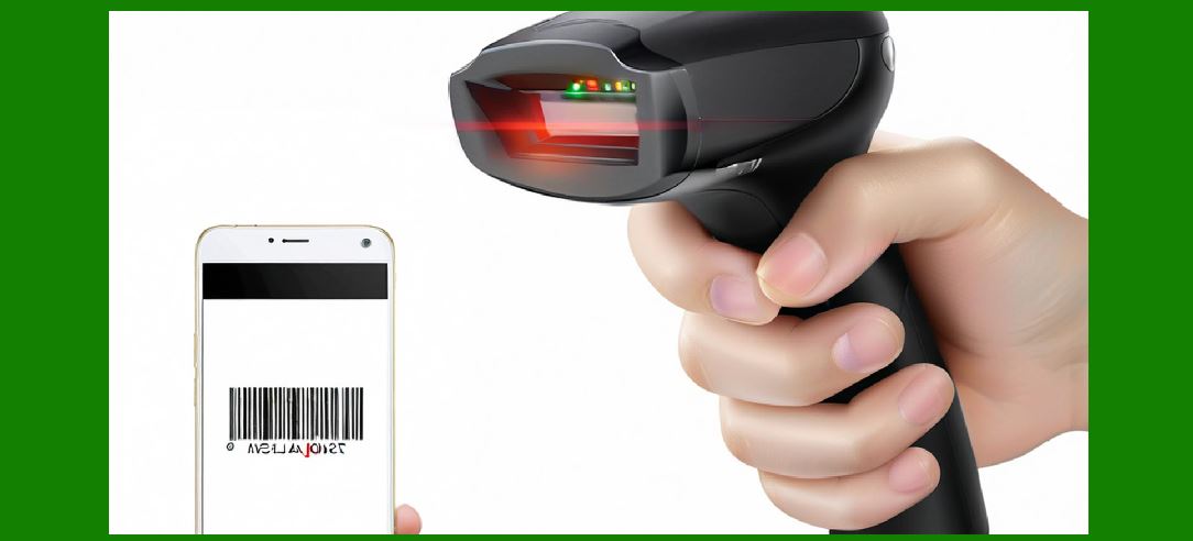
In a laser barcode scanner, the visible scanning line is not created by moving the laser diode itself. The diode stays fixed, emitting a continuous beam. The beam strikes a small mirror, and that mirror pivots rapidly back and forth, sweeping the beam across the barcode label and past it. The component that makes this happen is a resonant motor---often a tiny electromagnetic assembly with a flexural hinge or a torsional spring---that oscillates the mirror at its natural mechanical resonance, commonly around fifty cycles per second. |
The choice of fifty hertz is not arbitrary. It sits in a sweet spot where the mirror can complete a full sweep fast enough to feel instantaneous to a human operator, yet slow enough that the mechanical stress on the hinge remains manageable over years of use. More importantly, driving a mechanical system at resonance means the drive circuit only needs to supply small pulses of energy at precisely the right moments to sustain a large motion. Push a swing at its natural rhythm, and a small shove keeps it going. Push at the wrong rhythm, and the swing dies. |
The central engineering problem, and the subject of this article, is that the mirror's resonant frequency is not a fixed number etched into the motor. It is a moving target. Temperature changes alter the stiffness of the hinge material and the magnetic properties of the drive coil. Aging changes the effective mass and spring constant as materials fatigue and lubricants (or their absence) evolve. The drive circuit must therefore do something more sophisticated than simply output a fifty-hertz square wave and hope for the best. It must listen, or at least remember, and adjust. |
This requirement---track the resonance or lose the scan---is what separates a robust laser scanner from a fragile one. It also explains many of the field failures that technicians encounter in the real world, from handheld scanners in retail that grow weak with age to industrial scanners on conveyor lines that drift out of adjustment when ambient temperatures swing. |

|
2. Why Resonance, and Why Fifty Hertz |
Operating at mechanical resonance allows a small, efficient drive circuit to produce a large optical scan angle, but it makes the scanner dependent on continuous frequency tracking. |
A resonant scanning motor works like a tuning fork. When struck, it vibrates at a characteristic frequency determined by its geometry and material. Drive it at that frequency, and the amplitude builds. Drive it slightly off, and the amplitude falls sharply. In a scanner, the mirror is attached to a flexural element---a thin strip of metal or a torsion bar---that acts as the spring. A small permanent magnet on the moving assembly interacts with a stationary electromagnetic coil. When the drive circuit sends alternating current through the coil, the magnetic force nudges the mirror back and forth. If the nudges arrive at exactly the right phase relative to the mirror's motion, the swing grows until it reaches a designed limit or until the energy lost to friction and air resistance equals the energy injected each cycle. |
The practical benefit is enormous. A drive circuit that would need several watts to force a non-resonant mirror to sweep through a wide angle can sustain the same sweep at resonance with a fraction of that power. In a handheld scanner running on a battery, this efficiency determines whether the device lasts a shift or an hour. In an industrial scanner mounted above a conveyor, lower power means less heat and greater long-term reliability. |
The fifty-hertz figure reflects a balance among competing constraints. Lower frequencies, say twenty or thirty hertz, would produce a scan line that flickers visibly and may not sample a moving barcode fast enough to decode it before the package leaves the scan zone. Higher frequencies, say one hundred hertz or more, would increase the sampling rate but would also increase the mechanical stress on the hinge and the wear on the flexural element. Fifty hertz provides roughly fifty complete back-and-forth sweeps per second, which is fast enough for the decoder to capture multiple passes over a barcode in a small fraction of a second, yet gentle enough that a scanner can survive years of continuous operation. |
Some scanner designs use different resonant frequencies for different scan patterns. A single-line scanner might use a fifty-hertz horizontal sweep. A raster-scanning scanner that projects a pattern of multiple horizontal lines may use a slower vertical sweep, perhaps in the range of ten to twenty hertz, combined with the fast horizontal sweep to create a two-dimensional scan field. More elaborate designs can switch between resonant modes to produce different patterns for different decoding needs . In every case, however, the principle remains: the drive circuit must know where resonance lives at that moment. |

|
3. The Drift Problem: Why the Resonant Frequency Never Stays Put |
Temperature and aging both shift the resonant frequency of the mirror assembly, and the shift is large enough that a fixed-frequency drive will eventually fail to sustain adequate scan amplitude. |
The resonant frequency of a mechanical oscillator depends on two things: the stiffness of its spring and the mass that is moving. In a scanner mirror assembly, the spring is the flexural hinge, and the mass includes the mirror substrate, the magnet, and any mounting hardware. Anything that changes either the stiffness or the mass---or the distribution of that mass---changes the resonant frequency. |
Temperature is the most immediate and reversible cause of drift. The flexural hinge is typically made from a thin metal strip or a small torsion bar. Metals change their elastic modulus with temperature. As the scanner warms up from a cold start, or as the ambient temperature in a warehouse shifts from a winter morning to a summer afternoon, the hinge becomes slightly stiffer or slightly softer. The permanent magnet's field strength also changes with temperature, altering the force produced by a given drive current. The result is a resonant frequency that may shift by several percent across the rated operating temperature range. A scanner designed to run at fifty hertz at room temperature might find its true resonance at forty-eight hertz when cold or fifty-two hertz when hot. |
Aging produces a slower but equally inevitable drift. The flexural hinge undergoes millions or billions of flex cycles over its life. Even if the material never cracks, its microstructure can evolve. The epoxy or adhesive that bonds the mirror to the hinge may creep very slightly. The magnet may lose a fraction of its magnetization over years of exposure to heat and magnetic fields. The effective spring constant and effective mass both change, and the resonant frequency moves with them. |
The consequences of ignoring this drift are not subtle. When the drive frequency differs from the true resonant frequency, the mirror's oscillation amplitude drops. A scanner that once projected a wide, bright line across a label at twenty centimeters suddenly produces a narrow, dimmer line that only covers the label at ten centimeters. In the field, technicians describe this as the scanner 'getting weak' or 'losing range.' The laser diode may be perfectly healthy. The photodetector may be perfectly sensitive. The problem is that the mirror is no longer swinging wide enough to sweep the beam across the entire barcode symbol at the expected distance. |
A patent filing from the early 2000s described the situation precisely: when the mirror is driven at resonance, it may be driven to an amplitude five hundred percent larger than the operational value, but when driven significantly off resonance, the overall oscillating motion may be less than one percent of the operational value . That enormous sensitivity is the price of efficiency. Resonance gives you a large swing for free, but it also means that losing resonance takes the swing away almost entirely. |

|
4. How the Drive Circuit Tracks Resonance |
The drive circuit maintains scan amplitude by monitoring the mirror's motion or the motor's electrical response and adjusting the drive frequency to stay locked to the shifting resonance. |
The earliest and simplest approach to resonant motor drive was to set the drive frequency once at the factory and accept that the scanner's performance would degrade somewhat at temperature extremes or as the unit aged. This approach was common in inexpensive consumer scanners where the expected service life was short and the operating temperature range was narrow. It is almost never adequate for professional or industrial equipment, where a scanner may be expected to run for a decade in an unheated warehouse or a refrigerated loading dock. |
Modern drive circuits use feedback. The mirror assembly typically includes some means of sensing its position. In some designs, a small secondary coil picks up the magnetic field of the moving magnet, generating a voltage that oscillates in phase with the mirror's motion. In others, the drive coil itself serves double duty: the circuit measures the back-EMF generated by the moving magnet during the portion of the cycle when the coil is not being actively driven. Either way, the circuit obtains a signal that represents the mirror's actual motion, not just the command to move. |
From this signal, the circuit extracts the phase relationship between the drive pulses and the mirror's swing. At resonance, the mirror's motion lags the drive force by exactly ninety degrees. If the drive frequency is slightly too high, the phase relationship shifts in one direction. If it is slightly too low, it shifts in the other. The drive circuit uses this phase error as an error signal. It nudges its output frequency up or down until the phase error returns to the resonant value. This is a phase-locked loop, implemented in miniature analog circuitry or, in more recent designs, in a small microcontroller. |
The circuit also controls amplitude. Even at resonance, the mirror's swing depends on how much energy is injected each cycle. The drive circuit monitors the amplitude of the position signal and adjusts the width or height of its drive pulses to keep the swing at the designed value. If the mirror is swinging too little, the pulses get slightly wider. If it is swinging too much---which could stress the hinge---the pulses narrow. Some designs use mechanical travel stops to physically limit the maximum swing, allowing the drive circuit to be simpler and more tolerant of variations . The mirror assembly in a typical handheld scanner may be only a few millimeters across, but the control loop that keeps it oscillating is a complete little servo system. |
The practical difficulty is that the position signal is small and noisy. The back-EMF from a tiny magnet moving through a tiny coil is on the order of millivolts, riding on top of switching noise from the drive pulses and the laser diode current. Extracting a clean phase reference from this signal requires careful analog design: differential amplification, filtering, and careful grounding. When a scanner fails to maintain scan amplitude despite a healthy laser and a clean optical path, the fault often lies in this feedback path---a cracked solder joint on the position-sense coil, a dried-out capacitor in the filter, or a contaminated optical sensor in designs that use an optical position detector. |

|
5. Retail and Point-of-Sale: Where Scan Amplitude Determines Customer Experience |
In retail checkout, a scanner that loses scan amplitude manifests as slower transactions, frustrated cashiers, and customers who blame the store. |
The supermarket checkout lane is the most familiar deployment of laser scanning, and it is also one of the most demanding in terms of operator expectations. A cashier does not think about resonant frequency or phase-locked loops. The cashier knows only that the scanner should read the barcode the first time, almost every time, from a comfortable distance and at a natural angle. When that stops happening, the cashier compensates unconsciously: moving the item closer, tilting it, passing it back and forth over the window, sometimes lifting the scanner itself. Each of these compensatory behaviors adds seconds to the transaction. Across a busy lane, those seconds become minutes, and the checkout line grows. |
The resonant motor's health is directly tied to this experience. A scanner that has drifted out of resonance, or whose drive circuit has lost the ability to track the drift, will project a scan line that is shorter than the checkout window. Items passed over the far edges of the window---a large bag of dog food, a case of soda---will not be swept by the beam and will not decode. The cashier may assume the barcode is damaged or the item is mislabeled, when in fact the scanner's mirror is simply not swinging far enough. |
Temperature variation in retail environments is real, even if it is less extreme than in industrial settings. A scanner near a store entrance in winter operates in a draft of cold air every time the automatic doors open. A scanner in a sunny window display area may bake in direct sunlight for part of the day. The drive circuit's tracking loop is what keeps the scan amplitude stable through these swings, so that the cashier never notices. |
The aging dimension is equally important in retail because scanners are often kept in service far longer than their design life. A supermarket may install a scanner during a remodel and expect it to last through two or three subsequent remodels, a span of ten years or more. Over that time, the resonant frequency of the mirror assembly will drift. A drive circuit that was locked to the original frequency at manufacture will become progressively mismatched. The scanner will still work, but its effective scan zone will shrink year by year. The store may eventually replace the unit not because it has failed outright, but because it has become annoying to use---and the root cause is a motor drive that stopped following its mirror. |

|
6. Logistics and Warehousing: Scan Amplitude Under Harsh Conditions |
In warehousing and parcel logistics, laser scanners operate in wide temperature ranges and near constant vibration, making resonant frequency tracking a reliability necessity rather than a convenience. |
A distribution center is not a climate-controlled showroom. A scanner mounted above a conveyor line may see temperatures near freezing when the loading dock doors are open in January and temperatures above forty degrees Celsius near the roof in August. The same scanner may be subjected to the vibration of the conveyor itself, transmitted through its mounting bracket, and to the occasional impact of a misaligned package. |
Laser scanners in these environments are often fixed-mount units with oscillating mirrors that produce a broad scan pattern across the conveyor belt. The mirror's resonant motor runs continuously for hours at a time. The drive circuit's tracking loop is what allows the scanner to maintain a consistent scan width as the ambient temperature rises through the morning and falls again at night. Without tracking, the scan pattern would narrow during the hottest part of the day, precisely when package flow is often at its peak. |
A more subtle challenge in logistics is the interaction between vibration and resonance. The conveyor's vibration has its own frequencies, and if any of them happen to align with the mirror's resonant frequency, the mirror can be driven into unwanted oscillation by the environment rather than by its drive circuit. The drive circuit's feedback loop must distinguish between motion caused by its own drive pulses and motion caused by external vibration. In practice, this is handled by ensuring that the mirror's resonant frequency sits well away from the dominant vibration frequencies of typical conveyor systems, and by using travel stops that prevent the mirror from swinging beyond its designed limits even if external vibration adds energy . |
The consequences of poor frequency tracking in logistics are measured in missed parcels. A scanner with reduced scan amplitude may still read most barcodes, but it will miss labels that are placed near the edge of the scan zone or labels on packages that are slightly taller or shorter than the nominal height. These missed reads trigger exceptions: the package is diverted to a manual keying station, a human operator types in the tracking number, and the parcel's journey is delayed. In a facility handling tens of thousands of parcels per hour, even a small increase in the miss rate translates into significant labor cost and downstream delay. |
Some logistics operations have moved away from laser scanners toward image-based readers for exactly this reason. Image-based readers have no moving parts and therefore no resonant frequency to track . But laser scanners remain widely deployed because they are inexpensive, rugged in their own way, and capable of reading barcodes at distances and angles where image-based systems struggle. For as long as they remain in service, their motor drive circuits must do their quiet job of following the mirror's shifting resonance. |

|
7. Manufacturing and Automotive: Traceability Depends on a Steady Scan Line |
On factory floors, laser scanners read barcodes that link physical parts to digital records, and a shrinking scan line can break the chain of traceability. |
In automotive assembly, every major component carries a barcode or a two-dimensional code that identifies its part number, supplier, and production batch. As the component moves down the line, fixed-mount scanners read these codes at stations where the part must be verified before the next operation. A dashboard carrier, for example, may be scanned before the instrument cluster is installed, so that the assembly system knows it has the correct variant for that vehicle. A laser scanner with a weakened scan line may fail to read a code on a dark or low-contrast surface, or may fail to read a code that is slightly off-center on the carrier. |
The manufacturing environment adds its own stresses. Ambient temperature on a factory floor can vary significantly between a heated assembly area and a semi-open area near the loading docks. Dust and airborne oil mist from machining operations can coat the scanner's window and the mirror itself, reducing optical throughput. The drive circuit's amplitude control loop responds to some of this degradation by increasing drive power, but there are limits. A mirror that is physically dirty reflects less light, and no amount of drive-circuit cleverness can recover photons that never reach the barcode and never return. |
What makes manufacturing distinct from retail or logistics is the consequence of a missed read. In a supermarket, a missed read costs a few seconds. In a factory, a missed read can stop the line. The assembly system may refuse to advance a vehicle until a critical part's barcode has been verified, and the operator must then intervene with a handheld scanner or a manual override. Every minute of stopped production has a cost that is orders of magnitude larger than the price of the scanner itself. This is why industrial laser scanners are specified with wider temperature ranges, tighter frequency-tracking tolerances, and more robust feedback circuits than their retail counterparts. The resonant motor drive is not a commodity component in this context; it is a reliability-critical subsystem. |
Pharmaceutical manufacturing adds a regulatory dimension. Secondary package control---verifying that the correct carton, leaflet, and vial are assembled together---often relies on laser scanners reading codes at high speed. The scanner's scan amplitude must remain stable over a production campaign that may run for weeks. A drift in scan amplitude that causes intermittent missed reads is particularly insidious because it may not be noticed immediately. The line keeps running, but the read rate quietly drops from near-perfect to ninety-five percent, and the five percent of missed codes are either reworked or, worse, escape into the supply chain without proper verification. The drive circuit's tracking loop is part of the quality system, whether or not anyone thinks of it that way. |

|
8. Healthcare and Patient Safety: The Scanner That Must Not Fail |
In hospitals, barcode scanning is a patient safety intervention, and a scanner that reads unreliably can contribute to medication errors rather than prevent them. |
The use of barcode scanning at the point of care has grown dramatically over the past two decades. A nurse preparing to administer a medication scans the patient's wristband and then scans the medication label. The system verifies that the right patient is receiving the right drug at the right dose by the right route at the right time. If the scanner fails to read either barcode, the workflow is interrupted. The nurse may try again, or may resort to manual entry, which reintroduces the very human error that the barcode system was meant to eliminate . |
Laser scanners in healthcare settings are often handheld units, carried from room to room and used dozens or hundreds of times per shift. They are dropped, cleaned with harsh disinfectants, and left in hot or cold areas. The resonant motor inside a handheld scanner is subjected to mechanical shocks that a fixed-mount industrial scanner never sees. The flexural hinge must survive these shocks without cracking or permanently deforming. The drive circuit's tracking loop must continue to function even as the hinge's stiffness changes subtly from the cumulative effects of thousands of small stresses. |
A less obvious healthcare application is specimen tracking. Blood samples, tissue biopsies, and other laboratory specimens are labeled with barcodes at the point of collection and scanned at multiple points before analysis. A missed read at any of these points can delay a diagnosis or, in the worst case, cause a specimen to be misrouted. The scanners used in these workflows are often the same handheld laser units used for medication administration, which means the resonant motor's reliability affects not just medication safety but also diagnostic timeliness. |
Healthcare facilities also present a temperature-variation challenge that is easy to overlook. A scanner may be used in a warm patient room, then carried into a cool laboratory, then left in a sunny hallway. The drive circuit's ability to track the mirror's resonance across these small but rapid temperature changes determines whether the scanner reads reliably at each new location. A scanner that requires a minute to 'warm up' and regain full scan amplitude after moving from a cold corridor to a warm room is a scanner that will be perceived as unreliable, even if its actual failure rate is low. |

|
9. Field Diagnostics and the Symptoms of a Drive Circuit That Has Lost Track |
When a laser scanner underperforms, the symptoms often point to the resonant motor drive rather than the laser or the decoder, and understanding these symptoms helps technicians avoid unnecessary replacements. |
A technician servicing a scanner that 'won't scan' or 'scans only up close' follows a diagnostic path. The first suspect is usually the window: a smudged or scratched scan window attenuates both the outgoing laser beam and the returning reflected light. Cleaning the window is the first step, and it sometimes solves the problem. The second suspect is the laser diode itself: laser diodes do age, and their output power gradually declines. A power meter can confirm whether the diode is still emitting within specification. The third suspect, and the one most often overlooked, is the scan engine's resonant motor and its drive circuit. |
The symptoms of a drive circuit that has lost resonance tracking are characteristic. The scan line may still be visible, but it appears dimmer and shorter than normal. The scanner may read barcodes reliably at close range but fail at the distances where it used to work. The scanner may seem to 'struggle' with certain labels---not because the labels are poor quality, but because the shortened scan line only covers part of the label, and the decoder cannot assemble a complete symbol from the partial scans it receives. In some cases, the scanner may emit an audible whine or buzz that changes pitch when the unit is warmed or cooled, indicating that the drive frequency is hunting for resonance and not finding it cleanly. |
A technician who suspects the drive circuit can often confirm the diagnosis by measuring the drive signal at the motor coil. If the drive frequency is fixed and does not change when the scanner is gently warmed with a heat gun or cooled with a cold spray, the tracking loop is not functioning. If the drive frequency changes but the scan amplitude does not stabilize, the amplitude control loop may be faulty. In either case, the repair may involve replacing the scan engine assembly---the mirror, motor, and drive circuit are often integrated into a single sealed module---or, in some designs, replacing individual components on the drive board. |
The economic calculation matters. A handheld retail scanner may cost a few hundred dollars. Replacing the scan engine may cost a significant fraction of that, and the labor to diagnose and replace it adds more. In many cases, the scanner is simply replaced. But in industrial settings, where a single fixed-mount scanner may cost thousands of dollars and where replacement requires production downtime, repairing or recalibrating the drive circuit is often worthwhile. Understanding that the problem is a frequency-tracking failure, not a laser failure, prevents the unnecessary replacement of a perfectly good laser diode and focuses the repair on the actual fault. |

|
10. Design Tradeoffs: Why Not Just Use a Bigger Motor or a Stiffer Hinge |
The resonant motor drive exists in a web of tradeoffs, and every decision that makes the mirror easier to control in one way makes it harder to control in another. |
An engineer designing a scanner mirror assembly faces a series of interrelated choices. A stiffer hinge raises the resonant frequency and makes the mirror less sensitive to external vibration, but it also requires more drive force to achieve the same scan amplitude. A heavier mirror lowers the resonant frequency and increases the stored energy at a given amplitude, but it also increases the stress on the hinge during shocks and requires a stronger magnet and coil. A larger mirror collects more light and produces a brighter scan line, but its greater mass and moment of inertia make the resonance sharper and the frequency more sensitive to temperature. |
The drive circuit's tracking capability interacts with all of these choices. A mirror with a very high quality factor---a very sharp resonance---offers the greatest efficiency at resonance but the steepest drop in amplitude when the drive frequency is even slightly off. Such a mirror demands a very precise tracking loop with low noise and fast response. A mirror with a lower quality factor is more forgiving of frequency error but requires more drive power to sustain the same amplitude. The designer chooses the quality factor based on the application: a battery-powered handheld scanner may accept a sharper resonance and invest in a better tracking circuit to maximize battery life, while a line-powered industrial scanner may prefer a broader resonance and simpler drive electronics. |
The fifty-hertz operating frequency itself represents a similar tradeoff. A lower frequency would reduce the number of scans per second, giving the decoder fewer opportunities to capture a complete barcode before the label moves out of the scan zone. A higher frequency would increase the scan rate but would also increase the rate at which the hinge accumulates fatigue cycles. A scanner running at fifty hertz accumulates over four million cycles in a single day of continuous operation. Over a ten-year life, that is more than fifteen billion cycles. The hinge material must be chosen and processed to survive this without cracking, and the drive circuit must maintain precise amplitude control to avoid overstressing the hinge as it ages. |
These tradeoffs explain why scanner design is not a solved problem that can be reduced to a commodity. Two scanners that look identical from the outside may have very different internal mirror assemblies and drive circuits, optimized for different priorities: battery life, shock resistance, temperature range, or scan pattern complexity. The resonant motor drive is where these priorities meet the physical world. |

|
11. Detailed Summary: The Resonant Motor as the Scanner's Unseen Governor |
The resonant motor and its drive circuit form a closed-loop system that is essential to every laser scanner application, and the consequences of its failure ripple outward from the checkout lane to the hospital bedside. |
The scanning mirror in a laser barcode scanner is a small, fast-moving mechanical heart. It oscillates at approximately fifty hertz, driven by electromagnetic pulses that arrive in precise synchrony with its natural swing. This resonant operation is what makes laser scanning practical: it allows a small, low-power drive circuit to produce a large optical scan angle, which in turn allows the scanner to read barcodes across a wide window and at useful distances. |
But resonance is a relationship, not a setting. The mirror's natural frequency is a property of its materials, its geometry, and its condition. Temperature changes the stiffness of the hinge and the strength of the magnet. Aging changes the effective mass and the spring constant. Vibration from the environment can add or subtract energy from the mirror's motion. The drive circuit must therefore be more than a pulse generator. It must be a tracker, continuously or periodically measuring the mirror's response and adjusting the drive frequency to stay locked to resonance. |
The consequences of losing this lock are consistent across industries, even if the specific failure modes differ. In retail, a scanner that has drifted out of resonance produces a shortened scan line that misses barcodes at the edges of the checkout window, slowing transactions and frustrating cashiers. In logistics, a scanner that cannot maintain amplitude across a wide temperature range misses parcel labels during the hottest or coldest parts of the day, triggering manual exceptions and delaying shipments. In manufacturing, a weakened scan line causes intermittent missed reads on the assembly line, potentially stopping production or allowing unverified parts to advance. In healthcare, a scanner that reads unreliably at the bedside undermines the very safety system it was installed to support. |
The drive circuit's tracking loop is invisible to the user and rarely mentioned in product literature. It is not a feature that sells scanners. But it is the mechanism that makes the scanner's performance stable over time and temperature, and its absence or failure is the root cause of a large fraction of the 'weak scanner' complaints that service technicians encounter. When a scanner is replaced because it 'got old and stopped working,' the laser diode is often still healthy, the decoder is still capable, and the optics are still clear. What has failed is the quiet partnership between a mirror and the circuit that kept it swinging. |
For designers, the lesson is that the resonant motor drive deserves as much attention as the optical path and the decoding algorithm. For users and technicians, the lesson is that scan amplitude is a symptom worth watching. A scanner that gradually requires closer and closer barcode placement is not simply 'showing its age' in some vague sense. Its mirror is telling anyone who listens that its drive circuit has lost the rhythm. |
 cs@easiersoft.com