Summary: The derivative amplifier followed by a bandpass filter is the heart of the analog signal chain in a laser barcode scanner. This article explains, in plain language, what this filter does, why its center frequency sits in the tens of kilohertz, and why a modest Q of one to two is exactly right. It then travels through retail checkout, warehouse logistics, manufacturing lines, healthcare, and postal sorting to show how this humble filter quietly decides whether a scan succeeds or fails in each of those worlds. | 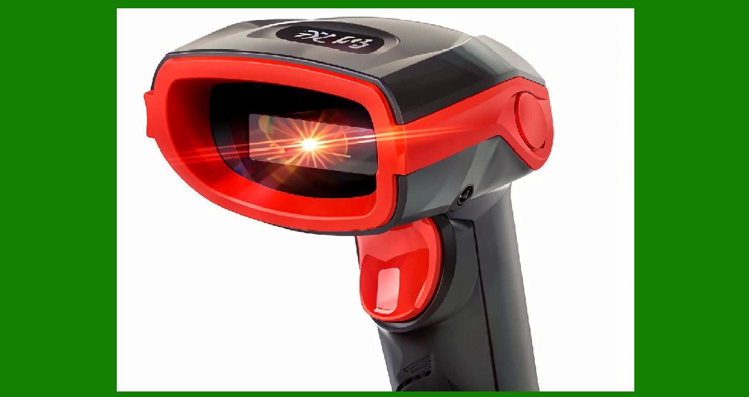
| 41. The Derivative Amplifier and the Bandpass Filter: Shaping the Flying Spot's Whisper | 1. Where We Are in the Signal Chain | The bandpass filter sits at the point where a noisy, messy analog pulse must be turned into something a decoder can trust. By the time the reflected laser light reaches the photodiode and then the derivative amplifier, the signal has already survived a journey. A tiny spot of light, perhaps a few thousandths of an inch across, has raced across a barcode at hundreds of inches per second. The light that bounces back is weak, modulated by the alternating dark bars and bright spaces, and contaminated by ambient room light, fluorescent flicker, and the inherent noise of the photodetector itself. The derivative amplifier takes this signal and emphasizes its changes, because the decoder ultimately cares about *edges*---the transitions from bar to space and back. But emphasizing change also emphasizes noise. The bandpass filter that follows is the gatekeeper that decides which frequencies of change are believable and which are junk. | Understanding what the derivative amplifier does requires a brief detour into why edges matter more than absolute brightness. In a perfect world, a barcode scanner would simply measure the reflectance of each point along the scan line. Dark bars would be low, white spaces would be high, and the decoder would count the durations. But the real world is not perfect. The laser spot has a finite size. The label may be curved, wrinkled, or printed with low contrast. The amount of light returning to the detector depends on the distance to the label, the angle of the label, and the color of the packaging. A decoder that relied on absolute brightness thresholds would fail constantly. By taking the time derivative of the signal, the scanner converts a problem of *level* into a problem of *slope*. A bar edge produces a steep slope regardless of whether the bar is printed in black ink on white paper or gray ink on cream paper. The derivative makes the signal more uniform across the incredible variety of labels a real scanner encounters. | The derivative operation, however, has a side effect that makes the bandpass filter absolutely necessary. Differentiation is a high-pass operation. It boosts high frequencies and attenuates low ones. That is good for edges, because edges contain high-frequency content. But it is also good for noise, because noise is broadband and often rich in high frequencies. The derivative amplifier will happily amplify the rapid fluctuations of fluorescent lamp flicker, the shot noise of the photodiode, and the electromagnetic interference picked up by the flexible cable connecting the scan head to the main board. If the derivative signal were fed directly into a comparator, the scanner would see edges everywhere and nowhere. The bandpass filter restores order by defining a window of frequencies where the *real* barcode information lives and rejecting everything outside that window. | 
| 2. What the Bandpass Filter Actually Does | A bandpass filter passes signals whose frequency content falls within a chosen band and attenuates everything else. In the context of a flying-spot scanner, the 'signal' is the derivative of the reflected light intensity as the spot sweeps across the barcode. The frequency of this signal depends on two things: how fast the spot is moving and how closely spaced the bars are. A spot moving at a hundred inches per second across a barcode with bars spaced ten thousandths of an inch apart will produce a fundamental frequency of roughly ten kilohertz. Denser codes or faster scan speeds push that frequency higher. Larger codes or slower speeds push it lower. The bandpass filter is tuned so that its passband covers the range of frequencies that real barcodes produce under real scanning conditions. | The center frequency of this filter is typically in the tens of kilohertz, and that number is not arbitrary. It emerges from the physics of the flying spot itself. Consider a typical handheld scanner with a scan rate of about forty scans per second and a scan angle of perhaps thirty degrees. At a working distance of six inches, the spot traverses the barcode in a few milliseconds. A standard retail barcode like UPC or EAN has modules that are thirteen thousandths of an inch wide. The resulting pulse train has a fundamental frequency somewhere between twenty and forty kilohertz. If the filter is centered too low, it will miss the fine detail of dense codes. If it is centered too high, it will miss the broad bars of large codes and amplify noise that carries no useful information. The tens-of-kilohertz region is the sweet spot where the majority of one-dimensional barcode information resides. | The Q factor of one to two is equally deliberate, and it reflects a trade-off between selectivity and robustness. Q is a measure of how narrow the filter's passband is. A high-Q filter, say Q equals ten or twenty, would be very selective, passing only a narrow slice of frequencies and rejecting everything else. That sounds desirable, but it creates a problem. Real barcodes are not pure sine waves. A barcode signal is a complex mixture of frequencies that changes from one scan to the next as the spot moves at slightly different speeds or crosses the label at a slightly different angle. A high-Q filter would ring and distort when presented with this shifting mixture, and it would be overly sensitive to variations in scan speed. A Q of one to two gives a broad, gentle passband that accepts the full range of frequencies a barcode might produce while still rolling off the extreme highs and lows where noise dominates. It is forgiving enough to handle the messiness of real scanning and selective enough to keep the decoder from drowning in noise. | A two-pole active filter is the standard implementation because it provides a good balance of performance and simplicity. The term 'two-pole' refers to the filter's roll-off characteristics: beyond the passband, the filter attenuates signals at a rate of forty decibels per decade. This is steep enough to suppress the high-frequency noise that the derivative amplifier boosted, and steep enough to reject the low-frequency fluctuations caused by label tilt and ambient light changes, but not so steep that the filter becomes finicky about component tolerances or introduces excessive phase distortion. Active filter designs using operational amplifiers are compact, inexpensive, and easy to tune during production. A passive filter made from inductors and capacitors would be bulkier and more susceptible to electromagnetic interference. The active topology also allows the filter to provide gain, compensating for the loss introduced by the differentiation stage. | 
| 3. Why This Stage Is the Quiet Decider of Scan Success | The bandpass filter is rarely the most visible part of a scanner, but it is often the component that determines whether a scan succeeds in difficult conditions. A scanner with a brilliant laser, a fast polygon mirror, and a powerful decoder will still fail if the analog signal reaching the digitizer is contaminated by noise or distorted by poor filtering. Field studies of scanner performance in real environments consistently show that the difference between a scanner that reads a wrinkled, poorly printed label on the first attempt and one that requires three or four attempts often comes down to the analog front end. The filter's job is to present the decoder with a signal that is as close as possible to the ideal: clean transitions, stable pulse widths, and no spurious edges caused by noise. | In retail checkout, the filter's ability to reject low-frequency interference is critical because the checkout environment is full of it. Fluorescent lighting, which is ubiquitous in supermarkets and department stores, modulates at twice the line frequency, typically one hundred or one hundred twenty hertz. The fluorescent tubes themselves flicker at this rate, and the electronic ballasts used in modern fixtures can produce higher-frequency harmonics as well. A shopper standing at the checkout counter may also be moving, casting changing shadows across the barcode. The derivative amplifier will pick up all of these slow variations and amplify them. The bandpass filter, with its lower cutoff frequency set well above the line frequency and its roll-off blocking the slow drift, ensures that the decoder sees only the rapid transitions of the barcode itself. Without this rejection, the decoder might interpret a flicker-induced fluctuation as a bar edge, producing a misread or a no-read. | The filter also plays a role in managing the trade-off between depth of field and resolution. Laser scanners are prized for their long depth of field compared to camera-based imagers . A scanner can read a barcode at the near end of its working range, where the spot is small and the signal is strong, and at the far end, where the spot is larger and the signal is weaker. But the frequency content of the signal changes across that range. At close range, the spot is small and the edges are sharp, producing higher-frequency components. At long range, the spot is larger and the edges are softer, shifting the signal energy toward lower frequencies. A single fixed bandpass filter must accommodate both extremes. The Q of one to two helps here: a broader passband covers the frequency spread across the working range, ensuring that neither near-field nor far-field scans are systematically disadvantaged. More sophisticated scanners sometimes use multiple filters or switchable filter banks to optimize for different ranges, but a single well-designed filter with a moderate Q handles the majority of retail scanning scenarios remarkably well . | 
| 4. Warehousing and Logistics: Speed, Distance, and Vibration | In warehouse environments, the bandpass filter faces a different set of challenges, dominated by speed and mechanical vibration. A distribution center handling e-commerce orders might process tens of thousands of packages per hour. Fixed-mount laser scanners positioned over conveyor belts must read barcodes on packages moving at speeds of several hundred feet per minute. At those speeds, the spot crosses a barcode in a fraction of the time it would take in a retail checkout, pushing the signal frequencies higher. The bandpass filter's center frequency and bandwidth must be chosen to accommodate this faster regime. A filter optimized for a slow handheld scanner would attenuate too much of the high-frequency content and produce a mushy signal that the decoder cannot resolve into distinct bars and spaces. | Ring scanners worn by warehouse workers present a related but distinct set of demands. These compact devices, worn on a finger and paired wirelessly to a terminal, allow workers to scan items while keeping both hands free for handling boxes . The scanning motion is generated by the worker's hand movement rather than by a motorized mirror, so the scan speed is variable and unpredictable. A worker reaching for a label on a high shelf might sweep the ring scanner across the barcode at one speed; the same worker scanning a label on a pallet at waist height might sweep at a completely different speed. The bandpass filter must be tolerant of this variability. A filter with a moderate Q and a passband broad enough to cover a range of hand-motion speeds will perform more consistently than a sharply tuned filter that assumes a fixed scan rate. The derivative amplifier and filter combination effectively normalizes the signal, making the decoder's job easier regardless of how fast or slow the worker moves. | Vibration is another source of low-frequency noise that the filter must reject. Conveyor belts vibrate. Forklifts rumble. Pallets drop onto loading docks. All of these mechanical disturbances can cause the scanner's optical assembly to shake, which translates into low-frequency modulation of the received light signal. If this modulation reaches the decoder, it can masquerade as a very wide bar or space, corrupting the timing measurements that the decoder uses to determine the widths of the barcode elements. The high-pass characteristic of the bandpass filter, combined with the derivative amplifier's emphasis on rapid changes, suppresses these mechanical artifacts. The filter's lower cutoff frequency is chosen to sit above the frequencies typical of mechanical vibration and below the frequencies typical of barcode information, creating a quiet zone where the real signal can pass unharmed. | The filter also helps with the problem of varying label quality in logistics. A package might carry a barcode printed on a laser printer, a thermal transfer printer, or an inkjet printer. It might be covered with clear tape that creates specular reflections. It might be scuffed or partially obscured by a shipping label. The derivative amplifier converts these variations into differences in signal amplitude, and the bandpass filter's gain stage can be designed to compensate. More importantly, the filter's rejection of out-of-band noise means that even a weak signal from a damaged label has a better chance of being decoded, because the signal-to-noise ratio within the passband is preserved. The decoder sees a smaller but cleaner pulse train rather than a larger but noisy one. Cleanliness wins. | 
| 5. Manufacturing and Industrial Traceability: Small Codes, Harsh Conditions | In manufacturing, laser scanners are often called upon to read codes far smaller than anything found in retail, and the bandpass filter's center frequency shifts accordingly. A typical industrial direct part mark might be a two-dimensional DataMatrix code etched onto a metal component or laser-marked onto a ceramic substrate. These codes can measure just a few millimeters across, with individual modules measured in tens of microns. When a flying-spot scanner reads such a code, the spot must be focused very tightly, and the resulting signal frequencies are much higher than those of a retail barcode. The bandpass filter's passband must extend to higher frequencies to capture this fine detail. At the same time, the filter must still reject the noise that inevitably accompanies high-bandwidth signal chains. The Q of one to two provides the necessary bandwidth to capture the fine code while still rolling off the highest-frequency noise components that would otherwise swamp the digitizer. | The LED manufacturing example illustrates how the analog front end must cope with variable print quality. A manufacturer producing hundreds of millions of LED units annually needed to track each unit through multiple production stages, including an oven process that reached approximately three hundred degrees Celsius . The two-dimensional codes, laser-marked onto the LED strips, sometimes became distorted by the heat. The manufacturer's initial scanning system could not achieve a perfect read rate, partly because some of the scanners were handheld units not designed for high-speed production lines . While the eventual solution involved high-resolution camera-based readers with specialized lighting, the underlying challenge is the same one that the bandpass filter addresses in laser systems: separating the signal of interest from the noise and distortion introduced by the environment. In a laser-based system, the filter's job would be to preserve the edges of the distorted code while rejecting the low-frequency variations caused by uneven illumination and the high-frequency noise caused by the harsh electrical environment of the production floor. | Industrial environments also expose scanners to electrical noise that would overwhelm an unfiltered front end. Welding equipment, induction heaters, variable-frequency motor drives, and high-power switching supplies all generate electromagnetic interference across a broad spectrum. The photodiode and its associated wiring act as antennas for this interference. The derivative amplifier, with its high-pass characteristic, amplifies the interference along with the signal. The bandpass filter's upper cutoff frequency is chosen to reject as much of this interference as possible while still passing the barcode signal. The two-pole roll-off is a compromise: a steeper filter would reject more interference but would also introduce more phase distortion and would be more sensitive to component variations. In practice, the moderate roll-off of a two-pole filter, combined with careful shielding and layout, provides adequate rejection for most industrial settings. | 
| 6. Healthcare and Laboratory Settings: Precision at Low Speeds | Healthcare applications often involve scanning at slower speeds than retail or logistics, which shifts the signal frequencies downward. A laboratory technician scanning a barcode on a sample vial or a patient wristband is not moving at conveyor-belt speed. The scan is deliberate and controlled. The barcode itself may be small, printed on a curved surface, and viewed at an awkward angle. Under these conditions, the signal frequencies produced by the flying spot are lower than those in a high-speed retail scanner. The bandpass filter's center frequency and bandwidth must be appropriate for this regime. A filter optimized for high-speed scanning would attenuate the low-frequency content of these slow scans, potentially causing the decoder to miss the broader elements of the barcode. | Clinical trial management and sample tracking rely on the reliability of the entire scanning chain, including the analog front end. A study of RFID and laser scanning technology in clinical trials noted that laser scanning offers high precision and high speed for reading barcodes and QR codes on trial materials, improving data accuracy and work efficiency while reducing human error . In a clinical setting, a misread is not merely an inconvenience; it can mean the wrong sample being assigned to the wrong patient or the wrong medication being administered. The bandpass filter contributes to this reliability by ensuring that the signal presented to the decoder is free of spurious transitions. When a technician scans a vial, the derivative amplifier and filter work together to produce a clean pulse train that accurately represents the widths of the bars and spaces, even if the label is slightly curved or the lighting is less than ideal. | The low-speed regime also means that the filter's rejection of low-frequency noise is particularly important. In a laboratory, the scanner may be used near centrifuges, incubators, and other equipment that produces vibration and electrical noise at low frequencies. The high-pass characteristic of the bandpass filter rejects this noise before it can reach the decoder. The derivative amplifier's emphasis on change means that a slowly drifting baseline, caused by the scanner being moved across a uniformly colored surface, is suppressed. Only the rapid transitions of the barcode produce significant output. This is the same principle that applies in retail, but the lower scan speeds in healthcare mean that the filter's lower cutoff must be set appropriately to avoid rejecting legitimate signal content. | 
| 7. Postal and Parcel Sorting: Throughput Above All | Postal sorting systems push flying-spot scanners to their limits in terms of speed and throughput. A major postal service might process millions of letters and parcels per day. Fixed scanners mounted over conveyor lines must read barcodes on items moving at high speed, often with varying orientations and at varying distances. The signal frequencies generated under these conditions can be quite high, and the bandpass filter must have sufficient bandwidth to pass them without excessive attenuation. At the same time, the sorting facility is an electrically noisy environment, with motors, conveyors, and sorting mechanisms generating interference. The filter's upper cutoff is critical: it must be high enough to pass the fastest scan signals but low enough to reject the interference that would otherwise corrupt the decoder's timing measurements. | The derivative amplifier and bandpass filter also play a role in handling the wide dynamic range of postal items. A letter envelope is thin and flat, presenting a barcode at a consistent distance from the scanner. A parcel might be bulky and irregular, with the barcode positioned at various angles and distances. The amount of light returning to the detector varies enormously. The derivative amplifier normalizes this to some extent by responding to changes rather than absolute levels, but the filter's gain and dynamic range must be adequate to handle the extremes. If the filter saturates on a strong signal from a nearby, highly reflective label, it will produce distortion that the decoder cannot resolve. If the filter's gain is too low, the weak signal from a distant, poorly printed label will be lost in the noise. The design of the filter must balance these competing demands, typically by using an active filter with carefully chosen gain and a passband that covers the expected range of signal frequencies. | The reliability of the bandpass filter directly affects the sortation accuracy and, ultimately, the cost of postal operations. A misread package must be manually handled, adding cost and delay. A no-read package may be rejected or routed to an exception queue. In a facility processing millions of items, even a small improvement in read rate translates into significant operational savings. The bandpass filter is one of many components that contribute to read rate, but it is a critical one because it sits at the boundary between the analog and digital domains. Once the signal is digitized, no amount of decoding cleverness can recover information that was lost or corrupted by poor filtering. The filter's job is to preserve the information content of the signal while discarding the noise, and in the high-throughput world of postal sorting, that job is performed under some of the most demanding conditions imaginable. | 
| 8. The Design Reality: Why This Stage Resists Change | The derivative amplifier followed by a two-pole active bandpass filter has remained essentially unchanged for decades because it works remarkably well. The fundamental physics of the flying spot has not changed. The frequencies produced by a laser spot sweeping across a barcode are determined by the scan speed and the code density, and those parameters have remained within a relatively narrow range across the vast majority of applications. The noise sources---ambient light, electrical interference, mechanical vibration---are also fundamentally the same. A design that was optimized in the 1980s for a retail scanner still performs well in a modern warehouse or laboratory, because the underlying problem is the same. | The Q of one to two represents a conservative choice that prioritizes robustness over theoretical optimality. A signal processing theorist might argue that a higher Q would improve the signal-to-noise ratio by rejecting more out-of-band noise. But the theorist's model assumes a stationary signal with a known frequency. Real barcode signals are non-stationary: their frequency content changes from scan to scan and even within a single scan as the spot accelerates and decelerates. A higher-Q filter would introduce ringing and phase distortion that would smear the edges the decoder needs to measure precisely. The moderate-Q filter accepts a slightly lower signal-to-noise ratio in exchange for preserving the temporal structure of the signal. In the world of barcode scanning, temporal fidelity matters more than raw signal-to-noise ratio. | The tens-of-kilohertz center frequency is similarly a product of practical compromise rather than theoretical optimization. It is high enough to pass the signal content of dense codes at typical scan speeds, and low enough to avoid the worst of the high-frequency noise that plagues wideband circuits. It sits above the flicker frequencies of artificial lighting and the mechanical resonances of handheld devices, and below the radio-frequency interference that can couple into the photodiode circuit. It is, in short, a frequency that is well-suited to the physical and electrical environment in which flying-spot scanners operate. | For engineers designing new scanners, the lesson of this stage is that analog signal conditioning still matters. It is tempting to imagine that a sufficiently fast analog-to-digital converter and a powerful digital signal processor could replace the analog filter entirely. In practice, this approach is rarely taken for flying-spot scanners. The dynamic range of the signal is too large, and the noise environment too hostile, for a digitizer to capture the raw signal without saturating or losing resolution. The analog bandpass filter performs an essential preprocessing step that reduces the demands on the digitizer and the decoder. It is a piece of circuit design that has been refined over decades, and it continues to earn its place in the signal chain. | 
| 9. Detailed Summary | The derivative amplifier and bandpass filter stage is the analog heart of the flying-spot laser scanner, and its design choices reverberate through every application. The derivative amplifier converts the photodiode's reflectance signal into an edge-emphasized signal, making the scanner's readings more uniform across the enormous variety of labels and conditions it encounters. The bandpass filter that follows, with a center frequency in the tens of kilohertz and a Q of one to two, defines the frequency window where genuine barcode information resides. The center frequency matches the physical reality of the flying spot: the speeds at which spots sweep across codes and the densities at which bars are printed. The moderate Q reflects a deliberate choice to prioritize robustness over selectivity, accepting a slightly wider noise bandwidth in exchange for tolerance of varying scan speeds and code densities. | In retail checkout, the filter rejects the low-frequency flicker of fluorescent lighting and the slow drift caused by shopper movement, ensuring that the decoder sees only the rapid transitions of the barcode. The moderate Q accommodates the frequency spread across the scanner's depth of field, from the sharp edges of near-field scans to the softer edges of far-field scans. | In warehouse and logistics environments, the filter must handle the high speeds of conveyor-belt scanning and the variable speeds of hand-held ring scanners. Its passband is broad enough to cover the range of signal frequencies produced by these different scanning motions, and its high-pass characteristic rejects the low-frequency vibration and mechanical disturbance that would otherwise corrupt the decoder's timing measurements. | In manufacturing and industrial traceability, the filter must pass the high-frequency content of very small codes while rejecting the intense electrical interference of the factory floor. The two-pole roll-off provides adequate noise rejection without introducing the phase distortion that a steeper filter would cause. | In healthcare and laboratory settings, where scanning is deliberate and slow, the filter's lower cutoff must be set appropriately to avoid attenuating legitimate low-frequency signal content. The filter's rejection of low-frequency noise from laboratory equipment contributes to the reliability that clinical applications demand. | In postal and parcel sorting, where throughput is paramount and the electrical environment is hostile, the filter's bandwidth and gain must balance the need to pass high-speed scan signals against the need to reject interference. The analog filtering stage performs a preprocessing function that no digital signal processor can fully replicate, because once the signal is digitized with inadequate analog conditioning, the information is lost. | 
| The enduring design of this stage---a derivative amplifier followed by a two-pole active bandpass filter with a center frequency in the tens of kilohertz and a Q of one to two---is a testament to the power of matching circuit design to physical reality. It is not a clever trick or a proprietary secret. It is a straightforward application of analog engineering principles to a well-understood problem. And it is the reason why a laser scanner can read a crumpled label on a moving conveyor, a tiny code on a ceramic substrate, and a barcode on a patient wristband with the same fundamental signal chain, adapted only in its details. The flying spot demands a great deal from the circuit that processes its reflections. The derivative amplifier and bandpass filter meet that demand with quiet, unglamorous reliability. |
|
 cs@easiersoft.com