Chapter 4. The TIA's Feedback Network: Where Gain Meets Bandwidth |
Summary |
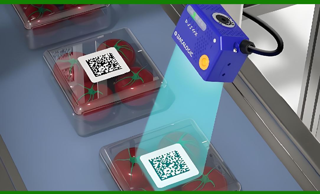
This chapter examines the transimpedance amplifier's feedback network as the decisive element that couples gain to bandwidth in every barcode scanner and optical sensing system. The pairing of a one-megaohm feedback resistor with a one-picofarad feedback capacitor creates a pole near one hundred sixty kilohertz---a frequency response adequate for the forty-kilohertz laser scan rates common in supermarket scanners but increasingly marginal as CCD clock rates climb. Through examples drawn from retail checkout, industrial sorting, medical diagnostics, automotive lidar, and scientific instrumentation, the chapter shows why this trade-off matters far beyond the laboratory bench. |
|
1. The Feedback Network as the Heart of the Front End |
Every barcode scanner begins with a photodiode that produces a tiny current proportional to the light it receives. That current might be measured in nanoamperes or even picoamperes. Before any decoding, any digitization, or any digital signal processing can occur, this current must become a voltage. The transimpedance amplifier performs this conversion, and its feedback network---a resistor and a capacitor in parallel---determines nothing less than what the scanner can see and how fast it can see it. |
The resistor sets the gain. A larger resistance produces a larger output voltage for the same input current. The capacitor, usually added not by explicit design choice but by the unavoidable parasitics of the circuit board and the resistor itself, sets the bandwidth. Together they form a low-pass filter whose corner frequency marks the boundary between signals the amplifier can faithfully reproduce and signals it will smooth into oblivion. |
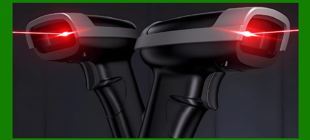
The specific pairing cited in this chapter's epigraph---one megaohm and one picofarad---produces a pole at roughly one hundred sixty kilohertz. That number deserves scrutiny because it sits precisely at the intersection of sufficiency and inadequacy for barcode scanning. A laser-based scanner sweeping its beam across a symbol at forty kilohertz produces a signal whose fundamental frequency content extends well above the scan rate itself, because the transitions between black bars and white spaces are sharp edges rich in harmonics. A one-hundred-sixty-kilohertz pole passes enough of that content for the scanner to distinguish bars of ordinary width. But when the clock rate of a CCD or CMOS image sensor pushes into the megahertz range, the same feedback network becomes a bottleneck that no amount of downstream digital cleverness can overcome. |

|
2. Why the Pole Exists: A Capacitor Nobody Ordered |
It is tempting to imagine that the feedback capacitor is a deliberate design choice, carefully selected to shape the frequency response. In many practical circuits, it is anything but. The one-picofarad capacitance that appears across a one-megaohm resistor often comes from the resistor's own parasitic capacitance, from the traces routing the feedback path across the printed circuit board, and from the input capacitance of the operational amplifier itself. A physical resistor is not a pure resistance; it has a small parallel capacitance that may reach a fraction of a picofarad, and at high frequencies that fraction matters. |
The consequence is that the designer does not simply choose a gain and then choose a bandwidth. The designer chooses a gain, and the bandwidth follows whether the designer likes it or not. For a barcode scanner operating at forty kilohertz, the resulting pole at one hundred sixty kilohertz provides a comfortable margin: the fourth harmonic of the scan signal sits at one hundred sixty kilohertz, so the amplifier passes the fundamental and the first few harmonics with reasonable fidelity while attenuating the higher frequencies that would otherwise contribute noise. This is not an accident of nature but a fortunate coincidence that early scanner designers learned to exploit. The feedback network they inherited from general-purpose operational amplifier practice happened to be well matched to the task. |
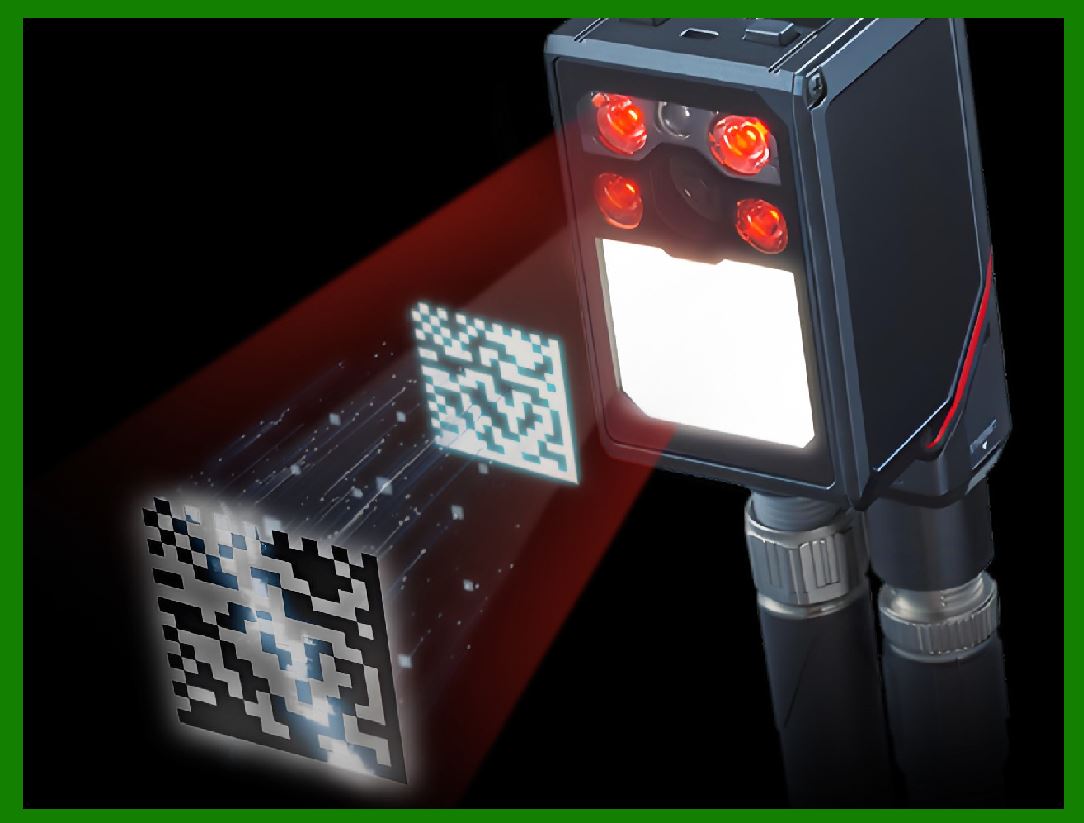
The marginality appears when the signal source speeds up. A CCD clock running at several megahertz produces charge packets that must be converted to voltage before the next clock cycle arrives. If the transimpedance amplifier's pole sits at one hundred sixty kilohertz, the output cannot settle in time. The result is not merely reduced amplitude but inter-symbol interference: one pixel's signal bleeds into the next, smearing the image and destroying the sharp transitions that barcode decoding depends upon. The same feedback network that serves a laser scanner admirably becomes a liability in a high-speed linear imager. |
|
3. Retail Checkout: Where the Trade-Off Was Perfected |
The supermarket checkout scanner represents the most familiar application of the transimpedance amplifier's gain-bandwidth compromise. A typical laser scanner sweeps a beam across a barcode at a rate between forty and one hundred hertz per scan line, with the polygon mirror or oscillating mirror producing many scan lines per second. The photodiode receiving the reflected light sees a signal whose envelope follows the bar pattern, but whose individual pulses correspond to the beam crossing the edges of each bar. These pulses have rise times determined by the beam spot size and the scan speed, typically in the range of a few microseconds. |
A transimpedance gain of one megaohm converts a photocurrent of, say, one microampere into an output voltage of one volt---a level comfortably above the noise floor of subsequent stages. The one-picofarad feedback capacitance limits the bandwidth to one hundred sixty kilohertz, which corresponds to a rise time of roughly two microseconds. That rise time is well matched to the optical pulse width produced by a beam crossing a standard barcode bar at typical scan speeds. The scanner can resolve bars as narrow as a few thousandths of an inch without difficulty. |
This match is not coincidental. The one-megaohm and one-picofarad combination became a de facto standard in barcode scanner front ends precisely because it worked well for the laser scan rates of the 1980s and 1990s. Millions of point-of-sale terminals were built around operational amplifiers whose feedback networks embodied this exact compromise. The engineers who designed them did not need to think deeply about pole placement because the parasitics did the job for them. The scanner industry grew up around a fortunate coincidence. |
The marginality emerges when retail moves to imaging scanners. A modern presentation scanner uses a two-dimensional image sensor rather than a swept laser beam, and the sensor's clock rate may exceed ten megahertz. The same one-megaohm gain that served the laser scanner now produces an output that cannot track the pixel clock. Designers must either reduce the feedback resistance, sacrificing signal-to-noise ratio, or accept a more complex multi-stage architecture in which the first stage provides moderate gain and wide bandwidth while later stages add gain at lower frequencies. The simple elegance of the single-stage transimpedance front end gives way to the realities of high-speed design. |

|
4. Industrial Barcode Scanning: Speed, Distance, and the Cost of Gain |
Warehouse and logistics operations impose requirements that retail checkout never faced. A package sorting conveyor may move at two meters per second, and the scanner must capture a barcode on a parcel that may be anywhere from a few centimeters to more than a meter from the scan head. The optical power returning to the photodiode drops with the square of the distance, so the transimpedance amplifier must extract a usable signal from a photocurrent that may be two or three orders of magnitude smaller than in the checkout aisle. |
The instinctive response is to increase the feedback resistance. Doubling the resistance doubles the output voltage for the same input current, improving the signal-to-noise ratio at the amplifier output. But doubling the resistance also halves the bandwidth, because the pole frequency is inversely proportional to the product of resistance and capacitance. At a distance of two meters, the beam spot on the barcode is larger, the edges are softer, and the signal bandwidth requirements are actually somewhat relaxed. The designer can afford a higher gain and a lower bandwidth. This is the trade-off working in the designer's favor. |
The trade-off turns against the designer when the same scanner must also read a barcode on a parcel that is only ten centimeters away, moving rapidly, with a sharp beam spot and a strong return signal. Here the bandwidth requirement is higher, and the signal is strong enough that gain is less critical. A fixed feedback network cannot serve both extremes optimally. Industrial scanner designers therefore often employ switched gain stages or variable feedback networks that can be reconfigured on the fly, or they accept a compromise feedback network and rely on the enormous dynamic range of modern analog-to-digital converters to handle both the near and far cases. The one-megaohm, one-picofarad starting point remains useful as a reference, but the production design departs from it. |
|
5. Medical Diagnostics: When Bandwidth Means Life and Death |
The transimpedance amplifier's gain-bandwidth trade-off appears in medical instruments with consequences that extend well beyond a failed scan. Pulse oximeters, which measure oxygen saturation by comparing the absorption of red and infrared light through a fingertip, rely on transimpedance amplifiers to convert the photodiode current into a voltage signal. The signal of interest is a small pulsatile component superimposed on a large static background, and its frequency content extends from the heart rate itself up to perhaps a few tens of hertz. Bandwidth requirements are modest; gain requirements are substantial because the pulsatile component may be only a fraction of a percent of the total signal. |
The situation changes dramatically in optical coherence tomography, a medical imaging technique that uses low-coherence interferometry to produce cross-sectional images of tissue. The interference signal detected by the photodiode contains frequencies determined by the scanning speed of the reference mirror and the depth range being imaged. Modern swept-source OCT systems operate at scan rates of one hundred thousand lines per second or more, and the resulting signal bandwidth can extend into the megahertz range. A one-megaohm transimpedance amplifier with a one-picofarad feedback capacitor would be utterly inadequate. |
Medical OCT designers therefore use transimpedance amplifiers with much lower feedback resistance, often in the range of a few kiloohms, and with operational amplifiers whose gain-bandwidth product reaches hundreds of megahertz. The lower resistance produces a smaller output voltage for a given photocurrent, but the photocurrents in OCT are relatively large because the technique uses a strong reference beam that interferes with the weak sample beam. The signal-to-noise ratio is preserved not by brute-force gain in the first stage but by careful optical design and balanced detection that cancels the excess intensity noise of the laser source. |
This example illustrates a crucial point about the feedback network: the optimal resistance is not a universal constant. It is determined by the photocurrent available, the noise characteristics of the operational amplifier, and the bandwidth required by the application. The one-megaohm figure that works well for a laser barcode scanner is wildly inappropriate for an OCT system, and the few-kiloohm figure that suits OCT would produce unusable noise levels in a low-light barcode application. |

|
6. Automotive Lidar: The Feedback Network Under Extreme Conditions |
The transimpedance amplifier's role in automotive lidar brings the gain-bandwidth trade-off into an environment where failure has consequences measured in human lives. A lidar system for autonomous driving or advanced driver assistance emits short pulses of laser light and measures the time of flight to reflected objects. The photodiode, often an avalanche photodiode that provides internal gain, produces a current pulse whose duration may be only a few nanoseconds. The transimpedance amplifier must convert this pulse to a voltage without excessive broadening, because the timing accuracy of the entire system depends on preserving the pulse's leading edge. |
A feedback network with a one-hundred-sixty-kilohertz pole corresponds to a time constant of roughly one microsecond, which is far too slow for nanosecond-scale lidar pulses. Automotive lidar designers use transimpedance amplifiers with bandwidths of tens or hundreds of megahertz, and they accept the correspondingly lower transimpedance gain. The LMH34400, for example, provides a fixed gain of forty kiloohms with a bandwidth of two hundred forty megahertz when driven by a photodiode with one picofarad of capacitance. The gain is forty times lower than the barcode scanner's one megaohm, but the bandwidth is fifteen hundred times higher. |
The automotive environment adds complications that barcode scanners never face. The lidar receiver must tolerate overload from a highly reflective target---a road sign, a license plate, a retroreflective vest---without blinding itself to subsequent returns from darker objects. The transimpedance amplifier must recover from saturation in nanoseconds rather than microseconds. It must operate over a temperature range from minus forty to plus one hundred twenty-five degrees Celsius. And it must do so while meeting automotive reliability standards that would make a consumer electronics designer blanch. The feedback network that satisfies these requirements is a carefully optimized compromise, not a default choice. |

|
7. Scientific Instrumentation: When the Signal Is Almost Nothing |
At the opposite extreme from lidar, ion mobility spectrometry and other analytical techniques demand transimpedance amplifiers that can measure currents of a few picoamperes while preserving bandwidths of tens of kilohertz. A drift-tube ion mobility spectrometer separates ions by their mobility through a carrier gas and measures the charge reaching a Faraday plate. The charge produces a current that may be as small as one nanoampere, and the signal's rise time may be approximately thirteen microseconds. |
The feedback resistance required to convert one nanoampere into a measurable voltage is enormous---on the order of one gigaohm. A single resistor of that value is physically unwieldy and its parasitic capacitance would ruin the bandwidth. Designers therefore use a T-network of resistors that multiplies the effective transimpedance gain without requiring an impractically large single component. The feedback capacitance must be correspondingly small, often in the femtofarad range, and the operational amplifier must have input bias currents measured in femtoamperes to avoid swamping the signal. |
The one-megaohm, one-picofarad feedback network that serves a barcode scanner would be catastrophically inadequate here: the gain is a thousand times too low, and the pole frequency, while nominally adequate for the signal bandwidth, would be degraded by the additional capacitance of the larger photodiode and the longer signal path. Scientific instrumentation transimpedance design is a discipline unto itself, driven by the fundamental physics of the measurement rather than by the economics of consumer products. |

|
8. The Feedback Capacitor as a Stability Element |
Throughout the preceding examples, the feedback capacitor has been treated as a bandwidth-limiting parasitic, an unavoidable consequence of physical construction. There is another perspective: the feedback capacitor is essential for stability. Without it, the combination of the photodiode's capacitance and the operational amplifier's input capacitance creates a zero in the noise gain that can cause the amplifier to oscillate. The one-picofarad capacitor in the barcode scanner's feedback network is not merely a bandwidth limiter; it is a compensation capacitor that ensures the amplifier remains stable across temperature and manufacturing variation. |
This dual role explains why the feedback capacitor cannot simply be eliminated to extend bandwidth. Removing it would increase the pole frequency, but at the cost of potential oscillation that would render the scanner completely inoperative. The designer's task is to choose the smallest capacitance that guarantees stability with adequate phase margin, thereby maximizing bandwidth while preserving reliable operation. The one-picofarad value typical of barcode scanners represents a practical equilibrium between these competing demands. |
The stability requirement becomes more demanding as the photodiode capacitance increases. A large-area photodiode, used when the available light is scarce, presents more capacitance to the amplifier's summing junction, pushing the noise-gain zero to a lower frequency and requiring a larger feedback capacitor to maintain stability. This is another manifestation of the gain-bandwidth trade-off: larger photodiodes collect more light but impose more capacitance, forcing a larger feedback capacitor and a lower bandwidth for the same transimpedance gain. |

|
9. Parasitics That Cannot Be Ignored |
The discussion of feedback capacitance has so far assumed a clean, well-controlled printed circuit board. Reality intrudes in the form of parasitic capacitances that add to the feedback network's total capacitance and degrade bandwidth in ways that the designer did not intend. The photodiode package contributes capacitance. The operational amplifier's input pins contribute capacitance. The traces routing the feedback path across the board contribute capacitance, and their contribution depends on layout details that are invisible on the schematic. |
A one-picofarad feedback capacitor is already small enough that a few tenths of a picofarad of stray capacitance represent a significant fraction of the total. At the one-megaohm gain level, the difference between one picofarad and one and a half picofarads is the difference between a pole at one hundred sixty kilohertz and a pole at one hundred six kilohertz. That difference may not matter for a laser barcode scanner operating at forty kilohertz, but it matters greatly for a scanner operating near the edge of its bandwidth budget. |
Experienced transimpedance designers therefore treat the feedback network not as two components but as a distributed system that includes the board layout, the component packages, and the photodiode itself. They guard the summing junction with a ring of copper connected to a quiet potential, they keep the feedback trace as short as possible, and they measure the actual bandwidth of the assembled circuit rather than trusting the schematic values. The gap between calculated and measured bandwidth is often twenty or thirty percent, and that gap can be the difference between a scanner that reads marginal barcodes reliably and one that does not. |

|
10. The Universal Lesson: No Free Gain |
The examples in this chapter span retail checkout, industrial logistics, medical imaging, automotive safety, and scientific research. In every case, the transimpedance amplifier's feedback network embodies the same fundamental constraint: gain and bandwidth cannot both be maximized. The one-megaohm and one-picofarad combination that serves a forty-kilohertz laser scanner so well becomes a bottleneck at higher speeds. The lower resistance and higher bandwidth that serve lidar would produce unacceptable noise in a low-light barcode application. The enormous resistance and femtofarad capacitance that serve ion mobility spectrometry would be physically impractical in a handheld scanner. |
This constraint is not a limitation of a particular technology that better components will someday overcome. It is rooted in the physics of the feedback loop itself. The feedback resistor's thermal noise increases with the square root of its resistance, while the signal increases linearly, so higher gain improves signal-to-noise ratio---but the pole frequency decreases inversely with resistance, so higher gain reduces bandwidth. The operational amplifier's gain-bandwidth product imposes an additional ceiling: the achievable transimpedance bandwidth cannot exceed the amplifier's gain-bandwidth product divided by the square root of the product of feedback resistance and total input capacitance. These relationships are as fundamental as the speed of light. |
The designer's art lies in recognizing which trade-off the application can tolerate. A barcode scanner can tolerate limited bandwidth because the scan rate is modest and the signal is strong. A lidar receiver can tolerate limited gain because the avalanche photodiode provides gain and the laser pulse is bright. An ion mobility spectrometer can tolerate limited bandwidth because the ion gate rise time is slow. Each application finds a different point on the same curve, and the feedback network is where that point is made real. |

|
Detailed Summary |
The transimpedance amplifier's feedback network---a resistor and capacitor in parallel---determines both the gain and the bandwidth of the optical front end in every barcode scanner and countless other optical sensing systems. The resistor converts photocurrent to voltage, and its value directly sets the transimpedance gain. The capacitor, whether deliberately chosen or inherited from parasitics, forms a low-pass filter with the resistor, establishing a pole frequency that marks the upper limit of usable bandwidth. A one-megaohm feedback resistor paired with a one-picofarad capacitor produces a pole at approximately one hundred sixty kilohertz, a value well matched to the forty-kilohertz scan rates of conventional laser barcode scanners but increasingly inadequate for high-speed CCD and CMOS imagers whose clock rates push into the megahertz range. |
The trade-off between gain and bandwidth is not a design flaw to be eliminated but a fundamental consequence of feedback circuit physics. Higher feedback resistance improves signal-to-noise ratio by amplifying the signal more than the resistor's thermal noise, but it reduces bandwidth by lowering the pole frequency. Lower resistance extends bandwidth but sacrifices the signal-to-noise ratio that weak optical signals require. The operational amplifier's gain-bandwidth product imposes an additional constraint: the achievable bandwidth depends on the amplifier's speed as well as the feedback network's values. |
Different industries navigate this trade-off according to their specific requirements. Retail barcode scanners accept the one-hundred-sixty-kilohertz pole because their laser scan rates and optical pulse widths are well matched to it, and the resulting gain provides ample signal for decoding. Industrial scanners that must operate over a range of distances and conveyor speeds often employ switched or variable feedback networks rather than accepting a single fixed compromise. Medical optical coherence tomography demands bandwidths in the megahertz range and therefore uses much lower feedback resistances, relying on strong reference-beam optical power to preserve signal-to-noise ratio. Automotive lidar requires nanosecond-scale pulse fidelity and uses transimpedance amplifiers with bandwidths of hundreds of megahertz and gains of tens of kiloohms, accepting the lower gain in exchange for the speed that time-of-flight measurement demands. Scientific instruments such as ion mobility spectrometers require extreme gain with modest bandwidth, achieved through T-network feedback structures and operational amplifiers with femtoampere input bias currents. |

|
The feedback capacitor serves a dual purpose beyond bandwidth limitation: it provides the phase compensation necessary to prevent oscillation when the photodiode's capacitance and the amplifier's input capacitance create a destabilizing zero in the noise gain. Removing the capacitor to extend bandwidth would risk instability, so the designer must choose the smallest capacitance that guarantees adequate phase margin. Parasitic capacitances from the photodiode package, the operational amplifier input, and the printed circuit board traces add to the feedback capacitance and can degrade bandwidth by twenty to thirty percent relative to the schematic values, making careful layout and empirical verification essential. |
The universal lesson of the feedback network is that no free gain exists. Every application must find its own balance point between sensitivity and speed, between the ability to detect weak signals and the ability to resolve fast ones. The one-megaohm and one-picofarad combination that became a de facto standard in barcode scanners represents one such balance point, elegant in its simplicity and well suited to its intended task. As optical sensing migrates toward higher speeds and greater sensitivities across industries from logistics to medicine to transportation, the feedback network remains the place where these competing demands are reconciled---and the place where the designer's understanding of the application's true requirements makes the difference between a circuit that works and one that merely functions. |
 cs@easiersoft.com