Summary |
Chapter 27 examines the illumination subsystem of a CCD barcode scanner: the bank of light-emitting diodes that floods the barcode with light so that the silicon sensor can see it. The chapter explains why red LEDs at 660 nanometers dominate, why white LEDs appear in certain applications, why the diodes are arranged symmetrically around the imaging lens, and why the driver circuit is almost always a switched-mode current source rather than a simple resistive ballast. The discussion stays deliberately practical. Instead of dwelling on circuit equations, it surveys how this illumination architecture plays out across retail checkout, warehouse logistics, healthcare, manufacturing, banking, and public-sector applications. The aim is to show that a seemingly minor design choice, the way a scanner lights up a label, shapes where and how CCD scanners can be used at all. |
|
1. Why Illumination Deserves Its Own Chapter |
A CCD scanner is, at bottom, a camera with a very specific job. It does not capture a photograph for a human to admire. It captures a line of brightness values, thousands of times per second, and hands those values to a decoder that looks for the pattern of dark bars and light spaces. The sensor itself is passive in the most literal sense: it accumulates charge in proportion to the photons that strike each photosite during an exposure window. If too few photons arrive, the signal drowns in the sensor's own noise floor. If the photons arrive unevenly, with hot spots and shadows across the barcode, the decoder may still succeed, but its margin for error shrinks. |
This is why illumination is not an afterthought. In a CCD scanner, the light source is an active participant in the optical system. It determines the contrast between bars and spaces, the effective depth of field over which a label can be read, and the amount of electrical power the handheld device must dissipate as heat. It also determines whether the scanner can read a label printed on glossy thermal paper, a label behind a plastic bag, or a label that has been scuffed by a hundred hands in a warehouse. |
The architecture described in this chapter, a bank of LEDs arranged symmetrically around the imaging lens and driven by a switched-mode current source, is the dominant solution for CCD scanners in the field. It is not the only possible solution. Laser scanners use a completely different illumination principle, sweeping a focused beam across the symbol. But for the class of scanners that image an entire barcode line at once onto a linear CCD array, the LED bank is the practical answer, and the reasons for its dominance reveal a great deal about how these devices are actually used. |

|
2. The LED Bank: Red, White, and Symmetric |
2.1 The Case for Red at 660 Nanometers |
Walk into any supermarket and watch a cashier scan a box of cereal. The scanner window may glow with a faint red light, or it may show no visible glow at all until the trigger is pulled. In most CCD scanners built for retail and logistics, the illumination comes from LEDs whose peak emission sits near 660 nanometers, a deep red just at the edge of human visual sensitivity. |
The choice of 660 nanometers is not arbitrary. Silicon photodiodes, the light-sensing elements inside a CCD, respond well across the visible and near-infrared spectrum, but their sensitivity curve is not flat. A typical CCD has strong response in the red and near-infrared and somewhat weaker response in the blue. Choosing a red LED at 660 nanometers means the light source and the sensor are reasonably well matched. The sensor can convert a useful fraction of the arriving photons into signal electrons, which matters when the exposure time is short and the light budget is tight. |
There is also a systems-level reason. Barcode labels are overwhelmingly printed in black ink on white paper or white synthetic stock. Black ink absorbs strongly across the visible spectrum, while white paper reflects strongly. In the red region around 660 nanometers, the contrast between black and white is excellent. The red light also passes through many colored packaging materials and laminates that would block or scatter shorter wavelengths, which helps when the label is behind a thin film or inside a poly bag. |
The 660-nanometer choice has a third, less obvious benefit: it is relatively easy to filter. A bandpass filter centered near 660 nanometers, placed over the scanner window, can reject a large fraction of ambient light from fluorescent tubes, sunlight, and the increasingly common white LED lighting in stores and warehouses. Ambient rejection is critical because a CCD scanner must work under whatever lighting the environment provides, from the dim aisles of a stockroom to the harsh glare of a loading dock at noon. |
|
2.2 When White LEDs Appear |
Red LEDs are not universal. Some CCD scanners use banks of white LEDs, which produce a broad spectrum that approximates daylight. The reason is usually image quality rather than barcode contrast. When a scanner is expected to capture additional information beyond the barcode, such as a photograph of a damaged package for a claims record or a color-coded label for a routing decision, white illumination preserves color information that red light would destroy. A red LED would render a blue sticker as nearly black and a red sticker as nearly white, which is unhelpful if the operator needs to distinguish them. |
White LEDs also appear in scanners designed for reading barcodes printed on colored backgrounds. A red barcode on a white label is unusual but not unheard of in certain manufacturing and inventory contexts. Under red illumination, red ink and white paper can appear nearly equally bright, and the barcode vanishes. White light, or a combination of red and white LEDs, restores the contrast. |
The trade-off is efficiency. White LEDs are typically blue emitters coated with a phosphor that converts part of the blue light into longer wavelengths. The conversion process loses energy, and the resulting spectrum includes wavelengths that the CCD may not detect as efficiently as 660-nanometer red. A white-LED scanner generally draws more current for the same exposure level, which matters in battery-powered handheld units. This is one reason why the red LED bank remains the default for high-volume scanning, while white illumination is reserved for scanners that need general-purpose imaging capability. |
|
2.3 Why Symmetry Matters |
The LEDs are arranged in a ring or a pair of arcs around the imaging lens. The lens sits at the center, looking out through the scanner window at the barcode. The LEDs flank it on both sides, or in a circular pattern, so that the illumination falls on the barcode from multiple directions at once. |
Symmetry solves a specific problem: specular reflection. When light strikes a glossy surface at a particular angle, it bounces off like a mirror rather than scattering in all directions. If all the illumination comes from one side, a glossy label can throw a bright reflection straight back into the lens, washing out the barcode entirely. A bank of LEDs arranged symmetrically distributes the illumination angles. The specular reflection from one LED may still reach the lens, but the reflection from another LED, arriving from the opposite side, may not. The decoder sees a barcode with uneven brightness but sufficient contrast, rather than a single blinding hotspot. |
Symmetry also improves uniformity across the field of view. A linear CCD sensor images a line that extends across the width of the barcode. If the illumination were concentrated at one end of that line, the decoder would see strong contrast at one edge of the symbol and weak contrast at the other. The bars and spaces at the dim end might merge into a gray blur. By placing LEDs on both sides of the lens, the illumination overlaps in the center and falls off more gradually toward the edges, giving the decoder a more consistent signal across the entire scan line. |

|
3. The Driver: Why Switched-Mode Current Sources |
3.1 The Problem with Simple Resistors |
The naive way to power an LED is to connect it to a voltage supply through a resistor. The resistor drops the excess voltage and sets the current according to Ohm's law. This works, and it is cheap, but it wastes power as heat in the resistor. In a handheld scanner running on a battery, wasted power translates directly into shorter runtime and a warmer grip for the operator. |
The waste becomes severe when the supply voltage is significantly higher than the LED's forward voltage. A red LED might drop about two volts when conducting. If the scanner runs from a five-volt rail, a simple resistor would burn off three volts as heat for every two volts that reach the LED. That is a sixty percent loss before any light is produced. In a device that may scan thousands of labels in a shift, the accumulated waste matters. |
3.2 The Switched-Mode Advantage |
A switched-mode current source takes a different approach. Instead of burning off excess voltage as heat, it switches a transistor on and off at high frequency, storing energy in an inductor during the on-time and releasing it to the LED during the off-time. By adjusting the duty cycle, the circuit can regulate the average current through the LED with far less resistive loss. Efficiencies of eighty percent or better are common, compared with fifty or sixty percent for a resistive driver. |
The switched-mode approach also handles the wide input voltage range that a scanner may encounter. A handheld scanner might run from a fresh battery at four and a half volts, a partially discharged battery at three and a half volts, or a USB port at five volts. A resistive driver would produce wildly different LED currents as the supply voltage changed, causing the illumination to dim or brighten unpredictably. A switched-mode current source holds the current steady regardless of input voltage, so the exposure conditions remain consistent from the first scan of the day to the last. |
There is a subtler benefit as well. The human eye does not perceive the high-frequency switching of a well-designed driver, but the CCD sensor can, if the switching frequency happens to align with the exposure timing. Good driver design places the switching frequency well above the frequencies that could interfere with the sensor readout, or synchronizes the driver to the sensor's timing so that the LED is on only during the exposure window and off during readout. This pulsed operation saves additional power, because the LED is not burning continuously between exposures. |
3.3 Pulsed Illumination and the Exposure Window |
In most CCD scanners, the illumination is not continuous. The LEDs flash on for a brief period, typically on the order of a millisecond or less, while the CCD accumulates charge. Then they turn off while the sensor shifts its accumulated charge out to the digitizer. This pulsed mode has two advantages. First, it reduces average power consumption dramatically. If the LED is on for ten percent of the time, the average current draw is roughly one-tenth of the peak current. Second, it freezes motion. A barcode moving past the scanner at arm's speed will blur during a long exposure. A short, bright flash captures a sharper image of the bars, improving decode reliability on moving targets. |
The switched-mode driver is well suited to pulsed operation because it can ramp the LED current up and down quickly. The inductor in the driver stores energy that can be delivered in a burst, and the control loop can adjust the pulse width to maintain the desired peak current even as the battery voltage sags. This is why the combination of a switched-mode current source and a symmetrically arranged LED bank has become the standard architecture for CCD scanners across industries. |

|
4. Retail and Point of Sale: The Illumination That Must Not Distract |
4.1 Supermarket Checkout |
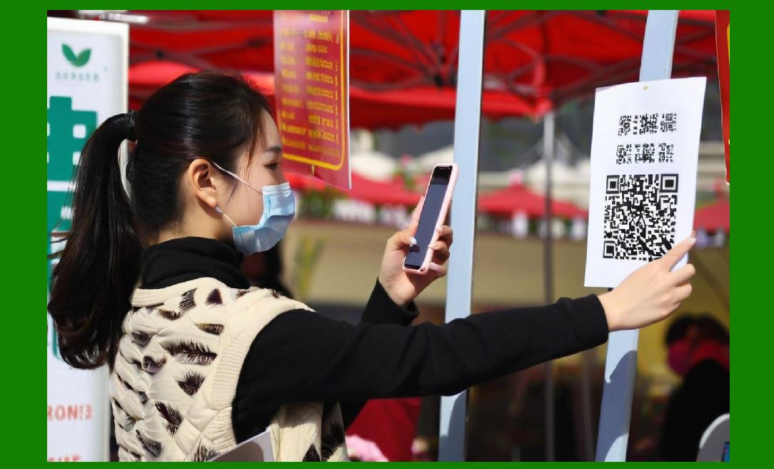
The supermarket checkout lane is the most visible deployment of CCD scanning technology, and it imposes a peculiar set of constraints on the illumination system. The scanner must read barcodes on products of wildly varying size, shape, and surface finish. A box of crackers has a flat, matte label. A bag of frozen peas has a curved, glossy film that reflects light unpredictably. A bottle of shampoo has a label wrapped around a cylinder, and the barcode may be oriented at any angle. |
The symmetric LED bank handles these variations by providing illumination from multiple angles. When the cashier drags a jar of pickles across the scanner window, the curved glass presents a moving series of reflection angles. A single illumination source would produce a flashing sequence of glare and shadow as the jar rotates. The ring of LEDs spreads the light around, so that at least some of the illumination strikes the barcode at an angle that does not reflect directly into the lens. The decoder sees a usable signal for a larger fraction of the scan time. |
The red color of the illumination is also a social consideration. A bright white light flashing every time a cashier scans an item would be visually intrusive in a retail environment. The deep red glow of a 660-nanometer LED bank is dim enough to be unobtrusive but bright enough for the CCD to capture a clean image. Customers rarely notice it, which is exactly what a retailer wants. |
4.2 Convenience Stores and Small Retail |
In a convenience store, the scanner may be built into a point-of-sale terminal with a small window facing the customer. The illumination system must be compact, because the terminal has limited space. A small bank of surface-mount LEDs arranged in a tight arc around a miniature lens can fit into a housing not much larger than a deck of cards. The switched-mode driver, likewise, can be built on a tiny circuit board with a single inductor and a controller chip. |
The scanning volume in a convenience store is lower than in a supermarket, but the variety of items is often higher. The same scanner may read a candy bar, a lottery ticket, a prepaid phone card, and a pack of cigarettes in quick succession. The illumination must adapt to labels printed on paper, cardboard, plastic film, and the metallic foil used on some tobacco packaging. Foil is particularly challenging because it is highly reflective and can act as a mirror. The symmetric LED arrangement helps by ensuring that the reflection from one LED is unlikely to align with the lens, even as the package angle changes. |
4.3 Self-Checkout |
Self-checkout stations introduce a different problem. The customer, not a trained cashier, positions the items. The scanner must tolerate imperfect placement, including labels that are partially covered by the customer's hand or oriented at an awkward angle. Some self-checkout scanners use a more powerful LED bank than a handheld unit, because the scanner is fixed and the customer may hold the item several inches away rather than placing it directly on the window. The brighter illumination extends the effective working range, so that a barcode held at a slight distance still receives enough light for a reliable exposure. |
The illumination in self-checkout systems also has a signaling function. Many scanners project a pattern of red lines or a red frame onto the scanning area, not to illuminate the barcode but to show the customer where to place the item. These aiming patterns are produced by separate LEDs or by diffractive optics, and they operate alongside the main illumination bank. The customer sees the red pattern, understands where to hold the product, and the CCD sensor captures the barcode under the illumination of the primary LED bank. |
|
5. Logistics and Warehousing: Illumination Under Duress |
5.1 Receiving and Putaway |
A warehouse receiving dock is not a gentle environment. Cardboard cartons arrive covered in dust, sometimes wet from rain, sometimes wrapped in shrink film that wrinkles and reflects light in unpredictable ways. The barcode label may be printed on thermal paper that has faded in the sun, or it may be a label applied by the supplier with low-contrast ink. |
CCD scanners used in this environment typically employ a relatively powerful LED bank. The illumination must penetrate a layer of dust or a scuffed plastic cover without requiring the operator to wipe the label clean. Red LEDs at 660 nanometers are effective here because thermal paper, which is used for most shipping labels, reflects strongly in the red. The black bars printed on thermal paper absorb the red light, producing a strong contrast even when the label is slightly dirty. The symmetric arrangement ensures that if one side of the label is shadowed by the carton's edge, the other side still receives light. |
The switched-mode driver matters in this environment for a practical reason: heat. A warehouse scanner may be used continuously for an eight-hour shift. If the driver were a resistive type, the heat generated inside the handle would become uncomfortable and would shorten the life of the battery and the electronics. The switched-mode driver's higher efficiency keeps the handle cooler and the runtime longer. |
5.2 Picking and Sorting |
In a pick-and-pack operation, the scanner is often mounted on a forklift or a wearable armband. The operator scans a location barcode on a shelf, then scans the item barcode, then scans a tote label. Each scan is a separate exposure, and the illumination flashes briefly for each one. The pulsed operation of the switched-mode driver conserves battery power between scans, extending the wearable unit's runtime to a full shift. |
The symmetry of the LED bank is particularly valuable when scanning shelf labels. These labels are often recessed or partially obscured by the shelf lip. The operator cannot always position the scanner directly in front of the label. An LED bank that illuminates from both sides increases the chance that enough light reaches the label even when the scanner approaches at an angle. The decoder may see a distorted or partially shadowed image, but the contrast between bars and spaces remains sufficient for a successful read. |
5.3 Cold Storage and Harsh Environments |
Warehouses that handle frozen goods operate at temperatures well below freezing. The air is dry, and condensation can form on the scanner window when a unit is moved between the freezer and the loading dock. The illumination system must continue to function when the window is fogged or frosted. A brighter LED bank, driven at a higher current during each pulse, can sometimes punch through a thin layer of frost by overdriving the exposure. The switched-mode driver's ability to deliver a high peak current for a short duration is essential here. A resistive driver sized for continuous operation would not have the headroom to produce the brief, intense flash needed to penetrate the frost. |
Cold temperatures also affect the LEDs themselves. The forward voltage of an LED increases slightly at low temperatures, and the light output can change. A well-designed switched-mode current source compensates for these shifts by adjusting the duty cycle to maintain the target current, so the illumination remains consistent whether the scanner is in a freezer aisle or a warm office. |

|
6. Healthcare: Illumination That Respects the Environment |
6.1 Patient Identification |
Hospitals and clinics use barcode scanning for patient wristbands, medication labels, and specimen tubes. The illumination requirements here are shaped by the clinical environment. Wristbands are often printed on synthetic materials that are designed to withstand hand sanitizer, soap, and water. They may be curved around a wrist, and the patient may be lying in bed under dim lighting. The scanner's LED bank must provide enough light to read the barcode without requiring the nurse to turn on the room lights. |
Red illumination is generally acceptable for wristband scanning, but some healthcare scanners use white LEDs to avoid any possibility of the red light being confused with clinical indicators. A red glow on a patient's wrist might be mistaken for a rash or a reaction by an anxious patient or family member. White light is more neutral and less likely to cause concern. The trade-off in power efficiency is acceptable in a hospital setting, where scanners are often docked and recharged frequently rather than used continuously for a full shift. |
6.2 Medication Verification |
Medication labels are small, often curved around a vial or a syringe, and printed with high-density barcodes that pack a lot of information into a small space. The illumination must be bright and uniform enough to resolve the narrow bars. A symmetric LED bank helps here by providing even illumination across the small field of view. The switched-mode driver maintains a stable current, so the exposure is consistent from vial to vial, reducing the chance of a misread that could have serious consequences. |
Some medication packaging uses low-contrast printing or colored labels that can confuse a scanner optimized for black-on-white. White LED illumination, combined with a sensor that can distinguish colors, allows the scanner to adapt its decoding strategy to the label's contrast characteristics. The illumination system is no longer just a light source; it is part of a sensing system that can be tuned to the application. |
6.3 Specimen Tracking |
Laboratory specimen tubes are among the most challenging barcode targets in healthcare. The label is wrapped around a cylindrical tube, often with a curvature that varies across the barcode's width. The label may be covered by a clear plastic film or a layer of condensation from cold storage. The barcode itself may be printed in a small font with thin bars. |
CCD scanners designed for specimen tracking often use a ring of LEDs that surrounds the tube as much as possible, illuminating the curved surface from all sides. The goal is to avoid a situation where the center of the barcode is brightly lit but the edges fall into shadow due to the curvature. The symmetric arrangement, combined with a driver that can deliver a strong pulse, produces a usable image even on a curved, reflective surface. |

|
7. Manufacturing and Industrial Automation: Illumination at Speed |
7.1 Work-in-Process Tracking |
On a factory floor, barcodes are often printed directly on metal parts, plastic housings, or circuit boards. The labels may be etched, laser-marked, or printed with specialized inks that have low contrast under visible light. The illumination system must be matched to the marking method. Laser-marked codes on metal often have poor contrast in the red region but better contrast under blue or white light. Some industrial CCD scanners use a combination of red and white LEDs, or interchangeable illumination modules, so that the same scanner can be optimized for different marking methods. |
The switched-mode driver is essential in industrial settings because the scanner may be mounted on a moving arm or a conveyor line, powered from a twenty-four-volt industrial supply rather than a battery. The driver must accept a wide input voltage range and deliver a stable current despite the electrical noise that is common on factory power lines. A well-designed switched-mode current source can reject much of that noise, keeping the illumination steady even when nearby motors and welders are switching on and off. |
7.2 High-Speed Sorting |
Automated sortation systems use fixed-mount CCD scanners to read barcodes on packages moving at high speed. The illumination must be intense enough to freeze the motion. A package moving at two meters per second will travel several millimeters during a one-millisecond exposure. If the exposure is longer, the barcode blurs and the decoder fails. The LED bank must deliver a very bright flash for a very short time. |
This is where the switched-mode driver's ability to deliver high peak currents becomes critical. The driver can charge an inductor during the interval between scans, then dump that stored energy into the LEDs in a brief, intense pulse. The peak current may be several times the continuous rating of the LEDs, but because the pulse is short and the duty cycle is low, the LEDs do not overheat. A resistive driver could not achieve this; it would be limited by the continuous power dissipation of the resistor and the LED. |
The symmetry of the LED bank also matters for high-speed sorting, because packages tumble and rotate as they move down the chute. A barcode that is facing away from one side of the scanner may be visible from the other side. Multiple scanners, each with its own symmetric LED bank, are often arranged around the conveyor to cover all possible orientations. |
7.3 Cleanroom and Electronics Manufacturing |
In electronics manufacturing, barcodes are used to track printed circuit boards through assembly and test. The environment is often a cleanroom with controlled lighting, and the scanner may be built into a test fixture. The illumination must not introduce particles or outgassing, so the LED bank is typically sealed behind a window. The red 660-nanometer LEDs are preferred because they produce less short-wavelength light that could degrade photosensitive materials on the boards. |
The low power dissipation of the switched-mode driver is also an advantage in a cleanroom, where excess heat can disturb the laminar airflow. A driver that wastes less energy as heat contributes to the stability of the environment. |

|
8. Banking, Finance, and Public Sector: Illumination for Documents and Identities |
8.1 Check and Document Processing |
Banks process millions of checks and documents, many of which carry barcodes for routing and tracking. These barcodes may be printed on paper that has been folded, stapled, or handled roughly. The illumination system in a document scanner must provide even light across a wide field of view, because the barcode may be anywhere on the page. |
CCD scanners used in document processing often use a long linear array of LEDs, arranged in a bar rather than a ring, to illuminate a wide strip. The principle is the same as the symmetric bank around a lens: distribute the light from multiple points so that no single reflection dominates. The switched-mode driver powers the entire array with a regulated current, ensuring that the illumination is uniform from one end of the bar to the other. If one LED in the array were to fail or dim, the decoder might see a dark band across the barcode, so the driver is designed to detect open or shorted LEDs and compensate or signal a fault. |
8.2 Identity Verification |
Barcodes on identification cards, driver's licenses, and passports are read at border crossings, polling places, and financial institutions. These documents often have laminated surfaces that are highly reflective. The illumination system must produce enough light to read the barcode through the laminate without being blinded by the reflection from the plastic surface. |
The symmetric LED arrangement is particularly effective here. The laminate acts like a mirror, but the mirror's angle depends on how the card is tilted. By illuminating from multiple directions, the scanner ensures that at least one LED's reflection does not point directly into the lens. The decoder can use the portions of the barcode that are not washed out by glare. Some identity scanners also use a polarizing filter in front of the lens, combined with polarized LEDs, to suppress specular reflection further. The illumination system and the optical filter work together as a single subsystem. |
8.3 Postal and Parcel Services |
Postal sorting centers handle envelopes and parcels at enormous rates. The barcodes on these items may be printed with inkjet printers that produce uneven dot patterns, or they may be hand-written in some contexts. The illumination must be bright enough to capture the barcode despite the uneven ink coverage, and the symmetric arrangement helps average out the variations. |
The switched-mode driver's efficiency matters in a postal sorting center for a different reason: the facility may have hundreds of scanners running simultaneously. A few watts saved per scanner translates into kilowatts saved across the facility, reducing both electricity costs and the heat load on the air conditioning system. The driver's pulsed operation also reduces the average power draw, which is important when the scanners are running continuously for hours at a time. |

|
9. The Illumination Subsystem as a Design Philosophy |
The details of the LED bank and the switched-mode driver may seem like narrow engineering concerns, but they embody a broader design philosophy that runs through the entire CCD scanner. The scanner is a device that must work reliably in the real world, not in a laboratory. The real world includes glossy labels, curved surfaces, dirty packaging, dim ambient light, bright sunlight, cold temperatures, and electrical noise. The illumination subsystem is the scanner's first line of defense against these conditions. |
The choice of 660-nanometer red LEDs reflects a compromise between sensor sensitivity, barcode contrast, ambient light rejection, and visual acceptability. The symmetric arrangement reflects the recognition that specular reflection is the enemy of reliable scanning, and that the best way to defeat it is to illuminate from many angles at once. The switched-mode current source reflects the understanding that power is precious in a portable device, and that efficiency is not a luxury but a requirement for usability. |
These principles are not unique to CCD scanners. Laser scanners face their own illumination challenges, though they solve them differently. Two-dimensional imagers, which use area sensors rather than linear arrays, have different illumination requirements because they capture a full image rather than a single line. But for the class of devices that this book calls CCD scanners, the LED bank and the switched-mode driver are the settled answer. They have been refined over decades of deployment in every industry where a barcode needs to be read. |

|
10. Detailed Summary |
This chapter has examined the illumination subsystem of a CCD barcode scanner, focusing on the two components that define it: the bank of LEDs arranged symmetrically around the imaging lens, and the switched-mode current source that drives them. |
The LED bank is typically composed of red emitters at 660 nanometers, a wavelength chosen because it matches the spectral response of silicon CCD sensors, provides strong contrast on the black-on-white barcodes that dominate commerce, penetrates many packaging films, and can be optically filtered to reject ambient light. White LEDs appear in scanners that need to preserve color information or read colored barcodes, at the cost of some efficiency. The symmetric arrangement of the LEDs, whether in a ring or a pair of arcs, serves two purposes: it distributes illumination angles to minimize specular glare from glossy surfaces, and it improves uniformity across the scan line so that the decoder sees consistent contrast from one edge of the barcode to the other. |
The switched-mode current source is preferred over a simple resistive driver because it wastes far less energy as heat, maintains a stable LED current across the wide input voltage range of battery-powered and industrial devices, and can deliver the high peak currents needed for short, bright exposure pulses. The pulsed mode of operation freezes motion, reduces average power consumption, and allows the driver to store energy between exposures. The driver's switching frequency must be chosen or synchronized to avoid interfering with the CCD readout. |
The practical consequences of this architecture were surveyed across several industries. In retail and point of sale, the red LED bank provides unobtrusive but effective illumination for barcodes on packages of every shape and surface finish, from matte cardboard to curved glass. In logistics and warehousing, the combination of a powerful LED bank and an efficient driver enables scanners to read dirty, faded, or condensation-covered labels in cold storage and on receiving docks, while keeping handles cool and batteries alive through long shifts. In healthcare, the illumination system adapts to wristbands, medication vials, and specimen tubes, with white LEDs sometimes chosen to avoid the clinical associations of red light. In manufacturing, the driver must tolerate industrial power noise and deliver the intense pulses needed for high-speed sorting, while the LED arrangement accommodates codes on metal, plastic, and curved surfaces. In banking, postal services, and identity verification, the symmetric illumination and efficient driver support the reading of documents and cards that are folded, laminated, or handled by the million. |
The illumination subsystem is not a passive accessory to the CCD sensor. It is an active optical component that determines where the scanner can be used, how quickly it can read, and how long it can run on a battery. The design choices embedded in the LED bank and the switched-mode driver, the wavelength, the symmetry, the efficiency, the pulse shaping, are responses to the real-world conditions that CCD scanners face in the field. Understanding these choices is essential to understanding why CCD scanners remain the workhorse of barcode reading in an era of increasingly sophisticated imaging technology. |
 cs@easiersoft.com