Chapter 13. The LED Is Driven by a Constant-Current Source, Often a Simple Transistor Current Mirror. No Modulation Is Used; the LED Stays On Continuously During a Scan. |
Summary of This Chapter |
This chapter examines the simplest illumination strategy found in any barcode scanner: a light-emitting diode that is driven by a constant-current source and remains steadily on for the entire duration of a scan. Unlike laser scanners that sweep a beam across the symbol, or modern imagers that flash arrays of LEDs in precise pulses, the wand scanner treats illumination as a background condition rather than an event. The LED does not blink, pulse, or modulate. It simply glows. The circuit that achieves this is correspondingly minimal, often nothing more than a pair of transistors arranged as a current mirror. We will explore why this design choice made sense for the wand form factor, how the constant-current source actually works in practice, and then survey a wide range of industries where this humble approach to illumination proved surprisingly durable. From the checkout counters of the 1980s to contemporary niche applications in field service and education, the continuously lit LED represents a distinct philosophy of engineering: do just enough, and do it reliably. |

|
1. The Wand Scanner as a Minimalist Machine |
Before we can appreciate the illumination circuit, we must understand the device it serves. The wand scanner, sometimes called a pen scanner or a wand reader, was among the first barcode readers to achieve widespread commercial adoption. It emerged in the early 1970s and remained a common sight in retail and inventory management through the 1980s and into the 1990s . Its form was deceptively simple: a pen-shaped housing containing a light source near the tip, a photodetector buried in the barrel, and a cable or wireless link carrying the resulting signal to a decoding unit. |
The operating principle of the wand was entirely manual. The user pressed the tip of the wand against a barcode label and dragged it across the symbol at a relatively steady speed. The light from the source reflected off the alternating dark bars and light spaces, and the photodetector converted those reflections into an electrical signal whose amplitude varied with the reflectivity of the surface passing beneath the tip. There was no scanning mirror, no oscillating motor, no spinning polygon. The human hand provided the scan motion. This had profound implications for every other subsystem in the device. If the scan speed was variable and unpredictable, there was little point in building sophisticated timing or modulation schemes into the illumination path. The LED simply had to illuminate the label brightly and consistently, and the decoding electronics had to cope with whatever signal emerged. |
The wand's simplicity was both its strength and its limitation. It was inexpensive to manufacture, rugged in construction, and required very little power. Those virtues made it ideal for applications where cost and durability mattered more than speed or range. A warehouse worker scanning inventory tags in a cold storage facility did not need a laser scanner that could read a label from three feet away. A clerk at a video rental store did not need omnidirectional scanning. What they needed was a device that worked every time it was dragged across a label, and that could be dropped, bumped, and generally abused without failing. The minimalist circuit philosophy served those needs well. |

|
2. Why Constant Current, and Why No Modulation |
The decision to drive the LED with a constant-current source rather than a voltage source is rooted in the physics of semiconductor light emitters. An LED's brightness is proportional to the current flowing through it, not the voltage across it. The voltage across a forward-biased LED is roughly fixed by its material properties, changing only slightly as current varies. If you attempt to control an LED with a fixed voltage source and a series resistor, the resulting current depends on the LED's forward voltage, which in turn drifts with temperature and varies from one manufacturing batch to the next. The result is unpredictable brightness. |
A constant-current source solves this problem by actively regulating the current to a target value, regardless of variations in the LED's forward voltage or the supply voltage. In the wand scanner, where the LED might be powered by a battery or a loosely regulated wall adapter, this regulation matters. The LED must produce enough light to generate a detectable reflection from the barcode, but not so much light that it wastes power or saturates the photodetector. A current mirror, built from two carefully matched transistors, provides this regulation with a minimum of components. |
The absence of modulation is a separate design decision, and a more interesting one. In later scanner architectures, particularly laser scanners and imaging engines, modulation serves several purposes. Pulsing the light source can reduce average power consumption while maintaining peak brightness. It can allow synchronous detection, in which the receiver looks only at signals at the modulation frequency, rejecting ambient light noise. It can even help with eye safety by spreading the optical energy over time. None of these advantages apply to the wand scanner. |
Consider the wand's operating conditions. The user drags the device across the barcode at a speed that might range from a few centimeters per second to perhaps half a meter per second. The resulting signal at the photodetector has frequency components that depend on the bar widths and the scan speed. For a typical retail barcode with bars on the order of a millimeter wide, and a scan speed of ten centimeters per second, the fundamental signal frequency is on the order of tens of hertz. This is an extremely low-frequency signal, close to the realm of slowly varying DC. A modulated illumination scheme would require the receiver to demodulate a very low-frequency envelope from a much higher carrier, adding complexity for no benefit. Synchronous detection at, say, ten kilohertz would indeed reject ambient light, but the wand's photodetector and amplifier were already designed to handle ambient light through other means, such as AC coupling and high-pass filtering. The simplest solution was to leave the LED on and let the photodetector see the barcode's reflection as a slowly varying current superimposed on a DC background. |
There is also a reliability argument. An LED that is never turned off experiences no thermal cycling. The junction temperature remains stable, the forward voltage remains stable, and the light output remains stable. For a device that might be used for thousands of scans per day over a period of years, this stability translates directly into consistent decoding performance. The constant-current source, by holding the current steady, further ensures that the LED's aging process is slow and predictable. A modulated LED, by contrast, experiences repeated heating and cooling cycles at whatever modulation frequency is chosen, which can accelerate degradation if the thermal design is not carefully managed. |
|
3. The Transistor Current Mirror in Practice |
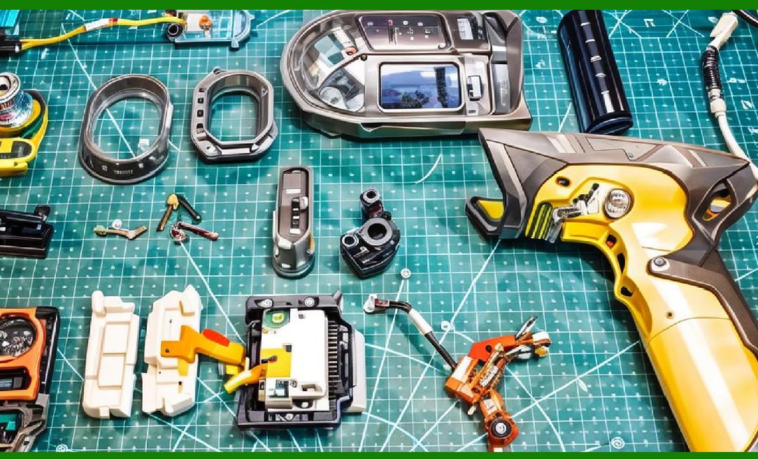
The phrase 'simple transistor current mirror' covers a family of circuits, but in the context of a wand scanner, the most common arrangement involves two bipolar junction transistors of the same type, fabricated on the same die or at least selected for matched characteristics. One transistor is configured as a diode-connected reference, with its base and collector tied together. The other transistor has its base connected to the base of the reference, and its collector drives the LED. The emitters of both transistors are tied to ground or to a common supply rail, depending on whether the mirror is sinking or sourcing current. |
When a reference current flows through the diode-connected transistor, it establishes a base-emitter voltage. That same voltage appears across the base-emitter junction of the second transistor, causing it to conduct a collector current that is related to the reference current by the ratio of the transistor geometries. If the two transistors are identical, the output current approximately equals the reference current. In practice, a small error arises from the finite current gain of the transistors, but for an LED driver in a barcode scanner, a few percent of error is entirely acceptable. The brightness of the LED varies by a few percent, the photodetector signal varies by a few percent, and the decoder, which is looking at ratios of bar widths rather than absolute signal levels, is unaffected. |
The reference current itself is typically set by a resistor connected between the supply voltage and the diode-connected transistor. The value of this resistor is chosen to produce the desired LED current, accounting for the supply voltage and the LED's forward voltage. In a wand scanner powered from a five-volt supply, with an LED forward voltage of perhaps 1.6 volts and a target current of a few milliamperes, the resistor value falls in the low kilo-ohm range. The exact value is not critical, as long as the resulting brightness is sufficient for the photodetector to see a clear signal from a barcode at the typical working distance of a wand, which is essentially zero, since the wand touches the label. |
What makes the current mirror attractive for this application is not precision but economy. Two transistors, one resistor, and the LED itself constitute the entire illumination subsystem. There is no inductor, no capacitor, no control loop, no oscillator. The circuit occupies a few square millimeters of printed circuit board space and costs perhaps a few cents in volume production. For a device that was designed to be manufactured in large quantities and sold at low prices, this economy was decisive. The wand scanner was never intended to compete with laser scanners on performance. It was intended to make barcode reading accessible to businesses that could not justify the cost of more elaborate equipment. |
The current mirror does have one practical limitation worth noting. If the supply voltage varies significantly, the reference current varies proportionally, and the LED brightness varies with it. In a battery-powered wand, this means the LED dims as the battery discharges. The photodetector amplifier must therefore have enough dynamic range to cope with a signal that might drop by thirty or forty percent over the battery's useful life. This is a manageable design challenge, but it illustrates the trade-off at the heart of the minimalist approach. Every simplification in one part of the system imposes a requirement elsewhere. The current mirror eliminates the need for a voltage regulator, but it shifts the burden to the receiver's dynamic range. |
|
4. The Photodetector's Perspective |
Although this chapter's focus is the LED driver, the illumination strategy cannot be understood in isolation from the receiver that depends on it. In a wand scanner, the photodetector is typically a photodiode operated in photovoltaic or photoconductive mode, feeding a transimpedance amplifier that converts the photocurrent into a voltage. The amplifier's output is then AC-coupled to remove the DC component corresponding to the average brightness of the label and the ambient light, leaving only the variations caused by the bars and spaces. |
This AC coupling is the receiver's answer to the continuously on LED. Because the LED never turns off, the photodetector always sees some baseline level of illumination, either from the LED reflecting off whatever surface the wand is touching or from ambient light entering the aperture. The AC coupling removes this baseline, allowing the amplifier to focus on the small, rapid changes that carry the barcode information. The high-pass corner frequency of the coupling network must be low enough to pass the barcode signal, which as we noted can be as low as tens of hertz, but high enough to reject slow drifts caused by the user's hand moving the wand across a surface of varying average reflectivity. |
There is a subtle interplay here between the constant-current drive and the receiver's filtering. If the LED current were allowed to drift slowly, the receiver's high-pass filter would reject the drift, and the barcode signal would be unaffected. The constant-current source is not strictly necessary for this reason; a simple resistor would also work, as long as the resulting brightness variations were slow compared to the barcode signal frequencies. The current mirror's advantage is primarily that it makes the brightness predictable and consistent from unit to unit, which simplifies manufacturing and ensures that every wand that comes off the line has adequate signal amplitude without individual calibration. |
The photodetector itself is often a silicon photodiode with a responsivity peak in the near-infrared, and the LED is typically chosen to emit at a wavelength that matches that peak, commonly around 900 to 950 nanometers. This wavelength is invisible to the human eye, which is a minor aesthetic advantage, and it also penetrates some inks and dyes that appear opaque in the visible spectrum. The constant-current drive ensures that the LED's emission spectrum remains stable, since the spectrum shifts slightly with drive current. A stable spectrum means a stable match between the LED output and the photodetector's responsivity, which in turn means a stable signal amplitude over the device's lifetime. |

|
5. Industry Applications: Where the Continuously Lit Wand Found Its Place |
5.1 Retail and Point of Sale |
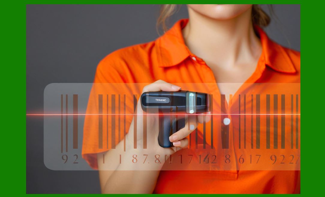
The wand scanner's first mass market was retail. In the 1970s and 1980s, before laser scanners became affordable, wands were the standard means of reading the Universal Product Code at checkout counters in grocery stores, drugstores, and department stores. The clerk would pick up the wand, drag its tip across the UPC label on each item, and the register would look up the price. The continuously on LED was perfectly suited to this environment. Checkout counters are typically well lit, so the LED did not need to be extraordinarily bright. The wand touched the label, so there was no need for focusing optics or long-range illumination. And the items being scanned were presented one at a time, at a pace set by the clerk, so there was no need for rapid-fire scanning. |
The retail environment also imposed a durability requirement that the minimalist circuit met admirably. Wands were routinely dropped on hard floors, bumped against shopping carts, and subjected to the general wear and tear of a busy checkout lane. A circuit with fewer components has fewer failure modes. The current mirror, with its two transistors and one resistor, was far less likely to fail than a more complex driver with oscillators, regulators, and protection circuitry. When a wand did fail, it was usually the cable or the connector, not the illumination circuit. |
|
5.2 Inventory and Warehouse Management |
Warehouses and distribution centers adopted wand scanners for inventory counting and stock location tracking. In these applications, the wand's ability to read labels that were printed on demand, sometimes on poor-quality thermal printers, was valuable. The continuously on LED provided consistent illumination that could penetrate the somewhat translucent paper used in some thermal labels, and the receiver's AC coupling handled the variations in average reflectivity as the wand moved from label to label. |
A distinctive warehouse application was the scanning of barcodes on shelving and racking. These labels were often placed at awkward angles or in locations that were difficult to reach with a handheld laser scanner. The wand's contact-based operation allowed a worker to reach up or down and drag the tip across the label without needing a clear line of sight for a laser beam. The LED's constant output meant that the scan would succeed regardless of the angle, as long as contact was maintained. This made the wand a tool of choice for cycle counting and location auditing in high-density storage environments. |

|
5.3 Libraries and Archives |
Libraries were early and enthusiastic adopters of barcode technology for tracking books and patrons. A barcode label on the inside cover or the back of each book, combined with a wand scanner at the circulation desk, allowed librarians to check items in and out with a simple drag of the pen. The continuously on LED was ideal for this application because it did not produce the bright red glare of a laser scanner, which could be distracting in a quiet reading environment. The wand's low power consumption also meant that it could be powered from the circulation desk computer's keyboard port or a small wall adapter, avoiding the need for bulky power supplies. |
The library environment also valued the wand's gentleness. Unlike a laser scanner, which projects a beam that might inadvertently shine into a patron's eyes, the wand's LED emitted only enough light to read the label at contact distance. The emission was diffuse rather than collimated, further reducing any eye safety concern. For a public institution serving children and the elderly, this was a meaningful advantage. |

|
5.4 Healthcare and Patient Identification |
Hospitals and clinics adopted barcode technology for patient identification and medication tracking, and the wand scanner played a role in early implementations of these systems. A barcode on a patient's wristband could be scanned with a wand to verify identity before administering medication or drawing blood. The wand's contact operation was actually preferable in this context, because it reduced the risk of scanning the wrong wristband. The nurse had to physically touch the wand to the correct band, which encouraged a deliberate, verified action rather than a casual point-and-shoot. |
The continuously on LED also had a practical benefit in patient rooms, which are often dimly lit at night. The wand's illumination was localized to the label being scanned, with minimal spill into the room. A laser scanner, by contrast, would project a visible line that could disturb a sleeping patient. The constant current drive ensured that the LED's brightness remained stable even as the device's battery aged, so that the nurse could rely on consistent performance without worrying about when the device had last been charged. |

|
5.5 Field Service and Utilities |
Field service technicians and utility meter readers used wand scanners in conjunction with portable data terminals to record their work. A technician repairing a piece of equipment might scan a barcode on the equipment's nameplate to log the service visit. A meter reader might scan a barcode on the meter to record the reading. In these outdoor and semi-outdoor environments, the wand's robust construction and simple illumination circuit were assets. There were no delicate optical components to misalign, no laser diode to fail, and no modulation circuitry to drift with temperature. |
The constant-current source was particularly important in these applications because the devices were often powered by rechargeable batteries that might be charged erratically or replaced with whatever was available. The current mirror's regulation kept the LED brightness within a usable range even as the battery voltage sagged under load or dropped as the charge depleted. The technician could continue working until the device's low-battery indicator came on, confident that the illumination was still adequate. |

|
5.6 Manufacturing and Quality Control |
On factory floors, wand scanners were used for work-in-progress tracking and quality control documentation. A worker might scan a barcode on a subassembly to record that it had passed a particular inspection station. The wand's ability to read labels that were curved, oily, or partially obscured was valuable in this environment, where laser scanners sometimes struggled with the specular reflections from machined metal surfaces. The LED's diffuse illumination was less sensitive to surface finish than a collimated laser beam, and the contact operation meant that the wand could be dragged directly across the label regardless of its orientation. |
The constant-current drive also contributed to the wand's suitability for manufacturing environments by eliminating a potential source of electromagnetic interference. A modulated LED driver, with its switching transients, could couple noise into nearby sensitive equipment. The constant-current mirror, operating in a steady DC state, produced no such transients. In a factory filled with precision instruments and control systems, this quietness was a small but real advantage. |

|
5.7 Education and Training |
One of the more unexpected niches for wand scanners was in education. Schools and training programs that taught barcode technology or inventory management often used wands as teaching tools because they were inexpensive, safe, and visually simple. A student could open a wand and see the LED, the photodetector, and the few components that made up the circuit. The constant-current mirror was easy to explain: two transistors, one resistor, a steady current, a steady light. This transparency made the wand an effective vehicle for teaching the fundamentals of optoelectronics and analog circuit design. |
The continuously on LED also made the wand safe for student use. There was no laser to cause eye damage, no high voltage, and no rapidly switching signals that might confuse an oscilloscope trace. A student could probe the current mirror with a multimeter and observe the stable voltage at the base of the transistors, confirming that the circuit was indeed regulating as described. The pedagogy matched the engineering: minimal, comprehensible, and reliable. |

|
5.8 Video Rental and Entertainment |
The video rental industry, at its peak in the 1990s, was a significant consumer of wand scanners. Rental stores used barcodes on cassette and DVD cases to track inventory and process rentals. The wand's low cost made it feasible to equip every checkout station, and its contact operation was well suited to the plastic cases, which could be scanned without removing them from the shelf or the return bin. The continuously on LED provided enough light to read the label through the clear plastic sleeve, and the receiver's AC coupling handled the variations in reflection as the wand passed over the label's surface. |
This application illustrates a general principle about the wand's market position. It was never the fastest or most capable scanner available, but it was often the most affordable and the most adaptable to the physical realities of a particular workplace. The video store clerk did not need to scan a DVD case from across the counter. The clerk needed to scan it right there, with the case in hand, and the wand did that reliably for years. |

|
6. The Enduring Logic of Simplicity |
The wand scanner's illumination circuit is, by any modern standard, primitive. A current mirror and a continuously on LED would be inadequate for a contemporary imaging scanner that must illuminate a two-dimensional barcode from a foot away while rejecting ambient light and managing power consumption. But the wand was not designed for those requirements. It was designed for a specific set of conditions: contact scanning, low cost, low power, and high reliability. Under those conditions, the minimalist approach was not a compromise. It was the correct engineering choice. |
The constant-current source, in particular, embodies a principle that runs through much of good circuit design. Regulate what matters, and ignore what does not. The LED's brightness matters, because it determines the signal amplitude at the photodetector. The LED's forward voltage does not matter, as long as the current is regulated. The supply voltage's exact value does not matter, as long as it is sufficient to keep the current mirror in regulation. By focusing on the one variable that affected performance and ignoring the others, the circuit achieved a level of robustness that more complex designs often struggle to match. |
The absence of modulation is a similar story. Modulation would have added components, added failure modes, and added design complexity, all to solve problems that the wand did not have. The wand's slow scan speed, contact operation, and AC-coupled receiver made modulation unnecessary. The engineers who designed these devices understood that every added feature carries a cost, and they chose to spend their complexity budget elsewhere, or not at all. |

|
7. Detailed Summary |
This chapter has examined the illumination subsystem of the wand scanner, focusing on the constant-current LED driver that was its defining feature. The key points are as follows. |
The wand scanner was a contact-based, manually operated barcode reader that emerged in the 1970s and remained in use for decades in cost-sensitive applications. Its illumination consisted of a single LED driven by a constant-current source, typically a simple transistor current mirror. The LED remained on continuously during a scan, with no modulation or pulsing. |
The constant-current drive was chosen because LED brightness is proportional to current, and a current mirror provides predictable brightness despite variations in supply voltage and LED forward voltage. The absence of modulation was appropriate because the wand's slow scan speed produced barcode signals at very low frequencies, making modulation unnecessary for signal recovery or ambient light rejection. The receiver's AC coupling handled the DC background from the continuously on LED. |
The current mirror circuit, typically two matched transistors and one resistor, offered minimal component count, low cost, and high reliability. Its limitations, primarily brightness variation with supply voltage, were managed by designing the receiver with adequate dynamic range. |
The wand scanner and its constant-current LED found applications across a remarkable range of industries. In retail, it enabled the first widespread deployment of barcode scanning at checkout. In warehouses, it provided durable, contact-based scanning for inventory management. Libraries used it for circulation because it was quiet and gentle. Healthcare adopted it for patient identification because contact scanning encouraged deliberate verification. Field service and utilities valued its robustness and battery-friendly operation. Manufacturing used it for work-in-progress tracking on surfaces that challenged laser scanners. Education used it as a teaching tool because its circuit was transparent and safe. The video rental industry equipped checkout stations with wands because they were affordable and effective. |
The minimalist circuit philosophy exemplified by the wand's LED driver remains relevant even in an era of highly integrated imaging engines. It serves as a reminder that the best circuit is often the one that does just enough, and that understanding the actual requirements of an application is more valuable than adding features that address problems the application does not have. The wand scanner's LED, glowing steadily through every scan, is a small monument to that principle. |
 cs@easiersoft.com